


16
7. TEMPERATURE
DISPLAYING
AND PARAMETERS CHANGING OR
SETTING
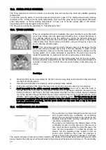
Displaying procedure:
Step 1:
You can browse the various options using the arrow buttons
and
on the panel.
Setting procedure:
Step 1:
To enter the functional parameters setting procedure press and hold the
button for about
15'' until PROG> is displayed.
Step 2:
When the next screen appears, the first parameter with its actual value will be shown.
Step 3:
You can move through the various options using the arrow buttons
and
on the panel.
Step 4:
With the parameter whose value is intended to be changed displayed, use the arrow button
to change the value; the parameter starts blinking. Using the buttons
and
the
parameter value is changed. As soon as the parameter will reach the requested value, it can
be stored pressing the
arrow.
Step 5:
To have other parameters changed you can browse them using the directional arrows
and
on the panel.
Step 6:
After being finished with parameters setting or modifying, in order to have them transferred
on the board non volatile memory press
button for about 10-15''.
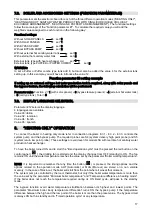
7.1. PROBES ENABLING AND DISABLING (FUNCTION PARAMETER #1)
To have each probe ON or OFF the parameter “Function parameter #1” must have a numeric value which is
the result of the weighted sum of all the probes:
S1 (solar panels circuit delivery
temperature)
1
S2
(heat
exchanger
low
temperature)
2
S3 (heat exchanger temperature)
4
S4 (system delivery temperature)
8
S5 (system return temperature)
16
The number is obtained by adding the weights of the required probes for the operation mode choosen by the
next parameter “Function parameter #2”.
Function parameter #1 setting example
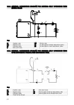
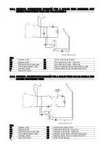
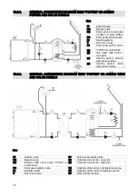
For example, if the boiler is intended to work in heating only mode, refer to schematic diagrams 8.3.1, 8.3.2,
8.3.3., must be present the two probes S4 and S5. Therefore the values 8 and 16 are added = 24. Setting the
value 24 the two required probes are abled.
Note:
In the evenience of problems during a probe installation, better you will have the two terminals on the board
for that probe wire bridged to avoid the warning message of missing or faulty probe being displayed.


