background image

- 8 -

System Overview

2.1. Dimensions

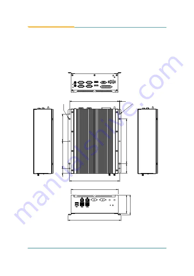
The following illustration shows the dimensions of each FPC-7601/7602/7603 

and FPC-7604, with the measurements in width, depth, and height called out.

2.1.1. FPC-7600

75.5 81.5

194.4

219

207

2

12-R2

20

Unit:mm

112

112

40

184

205

4-UNC#6-32 NUT

Optional Port

Optional Port

ANT. 1

ANT. 2

PWR

RST

Optional

VGA

DISPLAYPORT

DISPLAYPORT

COM 1

COM 2

COM 3

COM 4

SW

9-36V

+

DC IN

-

Summary of Contents for FPC-7600 Series

Page 1: ...1 FPC 7600 Series Robust Box PC with 3rd Generation Intel Core i5 i3 or Celeron Processor Platform User s Manual Version 1 2 2017 01 P N 4012760000120P...

Page 2: ...2 This page is intentionally left blank...

Page 3: ...i Revision History Version Release Time Description 1 0 2015 August Initial release 1 1 2015 October Add FPC 7600 model 1 2 2017 January Add Windows 10 to OS support driver path...

Page 4: ...kage 4 1 5 Ordering Information 5 1 5 1 Optional Accessories 5 1 5 2 Configure to Order Service 6 Chapter 2 System Overview 7 2 1 Dimensions 8 2 1 1 FPC 7600 8 2 1 2 FPC 7601 7602 7603 9 2 1 3 FPC 760...

Page 5: ...2 4 SATA Configuration 71 5 2 5 Intel R Anti Theft Technology Configuration 72 5 2 6 USB Configuration 73 5 2 7 F81866 Super IO Configuration 74 5 2 8 F81866 H W Monitor 76 5 2 9 Intel ICC 77 5 2 10 C...

Page 6: ...iv This page is intentionally left blank...

Page 7: ...rer Declaration of Conformity CE The CE symbol on the computer indicates that it is in compliance with the directives of the Union European EU A Certificate of Compliance is available by contacting Te...

Page 8: ...ve was published on 2 13 2003 The main purpose of the directive is to prohibit the use of lead mercury cadmium hexavalent chromium polybrominated biphenyls PBB and polybrominated diphenyl ethers PBDE...

Page 9: ...OVER THE OPENINGS 7 Position the power cord so that people cannot step on it Do not place anything over the power cord 8 Never pour any liquid into opening This may cause fire or electrical shock 9 Ne...

Page 10: ...whenever components are separated from the system Replacing Lithium Battery Incorrect replacement of the lithium battery may lead to a risk of explosion The lithium battery must be replaced with an i...

Page 11: ...misuse of or inability to use this product Vendor will not be liable for any claim made by any other related party Vendors disclaim all other warranties either expressed or implied including but not...

Page 12: ...x This page is intentionally left blank...

Page 13: ...1 1 Chapter 1 Introduction Chapter 1 Introduction...

Page 14: ...ugged Design for Shock Vibration Protection Memory Support up to 16GB DDR3 1 2 About this Manual This manual is meant for the experienced users and integrators with hardware knowledge of personal comp...

Page 15: ...t I O Ports Serial Port COM1 COM2 RS 232 COM3 COM4 RS 232 422 485 Selectable Selectable Port 1 x DB25 connector for 1 x digital I O 8 in 8 out or I O Expansion either one USB Port 2 x USB 2 0 ports 4...

Page 16: ...8 x 110 mm for FPC 7601 7602 7603 195 x 268 x 90 mm for FPC 7604 OS Support W7 Pro WS7E WE8 STD Windows 10 Power Requirement Power Input DC 9 36V input w 4 pin terminal block Power Consumption Max 65W...

Page 17: ...x PCIe x16 FPC 7603 Fanless system w 2 x PCI FPC 7604 Fanless system w 1 x PCIe x16 1 5 1 Optional Accessories The following items are normally optional but some vendors may include them as a standar...

Page 18: ...t WIFI AT2300 Atheros AR9462 Wi Fi module w 20cm internal wiring ANT D11 1 x Wi Fi Dual band 2 4G 5G antenna 3rd Generation Intel Core i3 3120ME L2 3M 2 4G 3rd Generation Intel Core i5 3610ME L2 3M 2...

Page 19: ...7 2 Chapter 2 System Overview Chapter 2 System Overview...

Page 20: ...7602 7603 and FPC 7604 with the measurements in width depth and height called out 2 1 1 FPC 7600 75 5 81 5 194 4 219 207 2 12 R2 20 Unit mm 112 112 40 184 205 4 UNC 6 32 NUT Optional Port Optional Po...

Page 21: ...9 System Overview 2 1 2 FPC 7601 7602 7603 Unit mm...

Page 22: ...10 System Overview 2 1 3 FPC 7604 Unit mm...

Page 23: ...and controls on the front and rear panels The following illustrations show all the components called out for all FPC 7600 Series 2 2 1 Front Views FPC 7600 Front No Description LAN ports Antenna hole...

Page 24: ...12 System Overview FPC 7601 7602 7603 Front No Description LAN ports Antenna hole Antenna hole Power button Reset toggle USB 3 0 ports USB 2 0 ports...

Page 25: ...13 System Overview FPC 7604 Front No Description LAN ports Antenna hole Antenna hole Power button Reset toggle USB 3 0 ports USB 2 0 ports...

Page 26: ...Take a look at the rear sides of FPC 7600 Series FPC 7600 Rear DC in DIO Selectable VGA DisplayPorts COM Ports 1 4 Line out Mic in FPC 7601 7602 7603 Rear PCI PCIe slots DC in DIO Selectable VGA Displ...

Page 27: ...15 System Overview FPC 7604 Rear DC in DIO Selectable VGA DisplayPorts PCIe Slot COM Ports 1 4 Line out Mic in...

Page 28: ...hs to find various drivers on the CD Windows 7 Driver Path Chipset Chipset Windows v10 0 13 SetupChipset exe USB 3 0 USB3 0 Setup exe VGA 32Bit Graphic WIN7_32bit_V_36_15_0_1073 Setup exe 64Bit Graphi...

Page 29: ...0 13 SetupChipset exe VGA 32Bit Graphic WIN10_32bit_V_153343_4425 win32_153343 4425 exe 64Bit Graphic WIN10_64bit_V_153343_4425 win64_153343 4425 exe LAN 32Bit Ethernet Win32bit PROWin32 exe 64Bit Eth...

Page 30: ...18 This page is intentionally left blank...

Page 31: ...19 3 Chapter 3 System Configuration Chapter 3 System Configuration...

Page 32: ...1 45 H1 H2 H4 H3 53 54 51 52 P10 P2 P9 P1 11 14 41 45 H1 H2 H4 H3 1 2 17 15 18 16 51 52 1 2 17 15 18 16 51 52 22 23 24 25 1 2 3 4 5 1 5 11 15 6 10 B1 B6 A1 A6 A5 A9 B5 B9 B1 B6 A1 A6 A5 A9 B5 B9 1 5 4...

Page 33: ...21 Engine of the Computer FMB i76M1 Board Bottom 1 1 1 1 7 6 5 4 3 2 1 7 6 5 4 3 2 1 B 2 B 1 A 1 A 2 B 8 1 B 8 2 A 8 1 A 8 2 B 2 B 1 A 1 A 2 B 3 1 B 3 2 A 3 1 A 3 2...

Page 34: ...21 39 40 22 1 19 20 2 L2 L1 1 3 2 4 1 2 4 3 1 1 1 1 2 5 6 1 2 5 6 1 2 5 6 10 9 2 1 4 3 2 1 25 26 1 2 53 54 51 52 P10 P2 P9 P1 11 14 41 45 H1 H2 H4 H3 53 54 51 52 P10 P2 P9 P1 11 14 41 45 H1 H2 H4 H3...

Page 35: ...P10 P2 P9 P1 11 14 41 45 H1 H2 H4 H3 53 54 51 52 P10 P2 P9 P1 11 14 41 45 H1 H2 H4 H3 1 2 17 15 18 16 51 52 1 2 17 15 18 16 51 52 22 23 24 25 1 2 3 4 5 1 5 11 15 6 10 B1 B6 A1 A6 A5 A9 B5 B9 B1 B6 A1...

Page 36: ...H1 H2 H4 H3 53 54 51 52 P10 P2 P9 P1 11 14 41 45 H1 H2 H4 H3 1 2 17 15 18 16 51 52 1 2 17 15 18 16 51 52 22 23 24 25 1 2 3 4 5 1 5 11 15 6 10 B1 B6 A1 A6 A5 A9 B5 B9 B1 B6 A1 A6 A5 A9 B5 B9 1 5 4 8 A...

Page 37: ...0 19 22 21 14 13 16 15 17 8 10 9 12 11 4 3 6 5 7 1 2 2 1 72 74 71 73 204 203 2 1 74 71 73 204 203 AT1 A1 A35 AT35 JTERM2 Description COM4 RS422 RS485 Terminator Selector Jumper Type Onboard 2 00mm pit...

Page 38: ...escription Serial ATA connectors for storage devices Connector Type 7 pin Serial ATA connector Pin Description 1 7 1 GND 2 TX 3 TX 4 GND 5 RX 6 RX 7 GND Board Bottom 1 1 1 1 7 6 5 4 3 2 1 7 6 5 4 3 2...

Page 39: ...cription Power connectors for SATA storage devices Connector Type 2 54mm pitch 1x4 pin DIP type connector Pin Desc 1 5V 2 GND 3 GND 4 12V 1 Board Bottom 1 1 1 1 7 6 5 4 3 2 1 7 6 5 4 3 2 1 B2 B1 A1 A2...

Page 40: ...UIM_VPP 35 GND 51 Reserved 17 UIM_C8 Reserved 52 3 3V 18 GND 19 UIM_C4 Reserved 52 51 16 18 15 17 2 1 Board Top 21 39 40 22 1 19 20 2 L2 L1 1 3 2 4 1 2 4 3 1 1 1 1 2 5 6 1 2 5 6 1 2 5 6 10 9 2 1 4 3 2...

Page 41: ..._VPP 35 GND 51 Reserved 17 UIM_C8 Reserved 52 3 3V 18 GND 19 UIM_C4 Reserved 52 51 16 18 15 17 2 1 Board Top 21 39 40 22 1 19 20 2 L2 L1 1 3 2 4 1 2 4 3 1 1 1 1 2 5 6 1 2 5 6 1 2 5 6 10 9 2 1 4 3 2 1...

Page 42: ...6 1 2 5 6 1 2 5 6 10 9 2 1 4 3 2 1 25 26 1 2 53 54 51 52 P10 P2 P9 P1 11 14 41 45 H1 H2 H4 H3 53 54 51 52 P10 P2 P9 P1 11 14 41 45 H1 H2 H4 H3 1 2 17 15 18 16 51 52 1 2 17 15 18 16 51 52 22 23 24 25 1...

Page 43: ...1 H2 H4 H3 53 54 51 52 P10 P2 P9 P1 11 14 41 45 H1 H2 H4 H3 1 2 17 15 18 16 51 52 1 2 17 15 18 16 51 52 22 23 24 25 1 2 3 4 5 1 5 11 15 6 10 B1 B6 A1 A6 A5 A9 B5 B9 B1 B6 A1 A6 A5 A9 B5 B9 1 5 4 8 A C...

Page 44: ...0 22 1 19 20 2 L2 L1 1 3 2 4 1 2 4 3 1 1 1 1 2 5 6 1 2 5 6 1 2 5 6 10 9 2 1 4 3 2 1 25 26 1 2 53 54 51 52 P10 P2 P9 P1 11 14 41 45 H1 H2 H4 H3 53 54 51 52 P10 P2 P9 P1 11 14 41 45 H1 H2 H4 H3 1 2 17 1...

Page 45: ...11 14 41 45 H1 H2 H4 H3 53 54 51 52 P10 P2 P9 P1 11 14 41 45 H1 H2 H4 H3 1 2 17 15 18 16 51 52 1 2 17 15 18 16 51 52 22 23 24 25 1 2 3 4 5 1 5 11 15 6 10 B1 B6 A1 A6 A5 A9 B5 B9 B1 B6 A1 A6 A5 A9 B5...

Page 46: ...9 40 22 1 19 20 2 L2 L1 1 3 2 4 1 2 4 3 1 1 1 1 2 5 6 1 2 5 6 1 2 5 6 10 9 2 1 4 3 2 1 25 26 1 2 53 54 51 52 P10 P2 P9 P1 11 14 41 45 H1 H2 H4 H3 53 54 51 52 P10 P2 P9 P1 11 14 41 45 H1 H2 H4 H3 1 2 1...

Page 47: ...601 7602 7603 only Configure to Order 1 1 USB4 USB1 Connector Type 1 x 5 pin wafer connector USB1 USB4 Pin Desc Pin Desc 1 5V 1 5V 2 D 2 D 3 D 3 D 4 GND 4 GND 5 GND 5 GND Board Bottom 1 1 1 1 7 6 5 4...

Page 48: ...51 52 P10 P2 P9 P1 11 14 41 45 H1 H2 H4 H3 53 54 51 52 P10 P2 P9 P1 11 14 41 45 H1 H2 H4 H3 1 2 17 15 18 16 51 52 1 2 17 15 18 16 51 52 22 23 24 25 1 2 3 4 5 1 5 11 15 6 10 B1 B6 A1 A6 A5 A9 B5 B9 B1...

Page 49: ...1 JTERM1 2 setting Board Top Rear Panel 21 39 40 22 1 19 20 2 L2 L1 1 3 2 4 1 2 4 3 1 1 1 1 2 5 6 1 2 5 6 1 2 5 6 10 9 2 1 4 3 2 1 25 26 1 2 53 54 51 52 P10 P2 P9 P1 11 14 41 45 H1 H2 H4 H3 53 54 51 5...

Page 50: ...38 This page is intentionally left blank...

Page 51: ...39 4 Chapter 4 Installation and Maintenance Chapter 4 Installation and Maintenance...

Page 52: ...rs is essential to open the computer and access the inside Follow through the steps below to remove the top cover and bottom cover from the computer 4 1 1 1 Remove Top Cover All jumpers MiniCard socke...

Page 53: ...r from the computer The inside of the computer comes to view FPC 7600 FPC 7601 04 To adjust jumpers or connect disconnect cables to from the main board see 3 2 Jumpers and Connectors on page 22 To ins...

Page 54: ...r FPC 7601 7602 7603 only PCI and PCIe connectors are all built on the bottom side of the main board To access these connectors the computer s bottom cover has to go Follow through the steps below to...

Page 55: ...he bottom cover from the computer FPC 7600 FPC 7601 04 The inside of the computer comes to view FPC 7600 FPC 7601 04 To install internal USB drives see 4 1 3 Install CPU on page 52 To install SATA sto...

Page 56: ...ule for particular applications There are another two notches at each left and right side of the memory module to help fix the module in the socket key notch side notch side notch To install a DDR3 me...

Page 57: ...ith the memory module s key notch aligned at the break of the SO DIMM s slot connector 5 Vertically plug the memory module to the DIMM socket Fully plug the memory module until both latches auto lock...

Page 58: ...has the bigger fin and the other has the smaller fin Each heat spreader comes with a thermal pad 2 Attach the memory module to the thermal pad side of the heat spreader with bigger fin See the pictur...

Page 59: ...iew from the other side 3 Attach the other heat spreader to the other side of the memory module so the two heat spreaders sandwich the memory module Be sure to align the two heat spreaders properly so...

Page 60: ...48 Installation Maintenance 4 Have the two metal clips Use them to hold the heat spreaders and the memory module together...

Page 61: ...49 Installation Maintenance Make sure the heat spreaders are clipped exactly as shown in the pictures below 5 Fully push the clips until they cannot be pushed any more See the pictures below push...

Page 62: ...elow The SO DIMM sockets are vertical type and each socket has two latches to fix the memory modules The memory module can only be installed by one direction due to the key notch 8 Pull back both latc...

Page 63: ...he memory module to the DIMM socket Fully plug the memory module until both latches auto lock the memory module in place key notch 11 Attach another thermal pad onto the top of the heat spreaders Ther...

Page 64: ...them safely for later use 3 The processor socket comes with a screw to secure the CPU As shown in the picture below loose the screw first before inserting the CPU 4 Place the CPU into the socket by m...

Page 65: ...nstall SATA Storage Devices The computer supports two 2 5 SATA storage devices to work inside the computer for RAID The following will gudie you to install two SATA HDD or SSD 4 1 4 1 Install SATA Sto...

Page 66: ...ce 3 For the 1st storage bracket Slide an HDD SSD storage device into the bracket FPC 7600 FPC 7601 04 4 Fix the storage device in place by using screws at the four screw holes on both sides of the br...

Page 67: ...orage device back into the computer by refastening the four screws SATA connectors Power connectors for SATA storage devices FPC 7600 FPC 7601 04 6 Connect the SATA signal cable s and power cable s FP...

Page 68: ...e below to install an PCI Express or PCI card to the computer To install a PCI or PCI Express card 1 Remove the bottom cover from the computer as described in 4 1 1 2 Remove the Bottom Cover on page 4...

Page 69: ...57 4 Use the screwdriver to loose the screw securing the lower expansion slot bracket...

Page 70: ...onfigure to order wireless modules available with the computer is the Wi Fi moldue WIFI AT2300 WIFI AT2300 Atheros AR9462 Wi Fi module w 20cm internal wiring See also 1 5 2 Configure to Order Service...

Page 71: ...r upside down on a flat surface Find the eight screw holes at its bottom as marked in the red circles in the illustration below 2 Have the two wall mount brackets Use the screws included in the wall m...

Page 72: ...follow every grounding requirement in your place Warning Whenever the unit is installed the ground connection must always be made first of all and disconnected lastly 1 See the illustration below Remo...

Page 73: ...wer source 4 Identify the positive and negative feed positions for the terminal block connection See the symbols printed on the rear panel indicating the polarities and DC input power range in voltage...

Page 74: ...62 This page is intentionally left blank...

Page 75: ...63 5 Chapter 5 BIOS Chapter 5 BIOS...

Page 76: ...Date and Time 07 14 2015 10 09 20 System Language English System Date Thu 07 15 2015 System Time 14 50 28 Access Level Administrator Choose the system default language Advanced Chipset Boot Security...

Page 77: ...nt screen and return to the top menu Page Up Increases current value to the next higher value or switches between available options Page Down Decreases current value to the next lower value or switche...

Page 78: ...ter Select Change Opt F1 General Help F2 Previous Values F9 Optimized Defaults F10 Save Exit ESC Exit Version 2 17 1247 Copyright C 2015 American Megatrends Inc The BIOS info displayed are Info Descri...

Page 79: ...Opt F1 General Help F2 Previous Values F9 Optimized Defaults F10 Save Exit ESC Exit The featured settings and submenus are Setting Description ACPI Settings See 5 2 1 ACPI Settings on page 68 S5 RTC...

Page 80: ...American Megatrends Inc Main Select Screen Select Item Enter Select Change Opt F1 General Help F2 Previous Values F9 Optimized Defaults F10 Save Exit ESC Exit Setting Description Enable Hibernation En...

Page 81: ...Help F2 Previous Values F9 Optimized Defaults F10 Save and Exit ESC Exit Advanced Disabled Disabled The featured settings are Setting Description Wake System with Fixed Time Sets if to awake the syste...

Page 82: ...CPU caches See the depiction below CPU Configuration Intel R Core TM i5 3610ME CPU 2 70GHz CPU Signature 306a9 Microcode Patch 10 L1 Data Cache 32 kB x 2 L1 Code Cache 32 kB x 2 L2 Cache 256 kB x 2 L3...

Page 83: ...nable or disable SATA Device Version 2 17 1246 Copyritght C 2015 American Megatrends Inc Advanced Aptio Setup Utility Copyright C 2015 American Megatrends Inc Select Screen Select Item Enter Select Ch...

Page 84: ...en Select Item Enter Select Change Opt F1 General Help F2 Previous Values F9 Optimized Defaults F10 Save and Exit ESC Exit Advanced Intel R Anti Theft Technology Configuration Intel R Anti Theft Techn...

Page 85: ...1 Keyboard 3 Hubs Legacy USB Support Enabled USB3 0 Support Enabled USB Devices USB Configuration Select Screen Select Item Enter Select Change Opt F1 General Help F2 Previous Values F9 Optimized Defa...

Page 86: ...C 2015 American Megatrends Inc Select Screen Select Item Enter Select Change Opt F1 General Help F2 Previous Values F9 Optimized Defaults F10 Save Exit ESC Exit Set Parameters of Serial Port 1 COMA Su...

Page 87: ...2 is the default Serial Port 4 Configuration Configures the computer s COM4 which is fixed to RS232 and cannot be changed The featured settings are Setting Description Serial Port Enables disables the...

Page 88: ...ature 50 C System temperature 53 C VCORE 1 748 V 5VSB 5 087 V 5V 4 945 V 12V 12 320 V Version 2 17 1247 Copyright C 2015 American Megatrends Inc Advanced Chipset Boot Security Save Exit Aptio Setup Ut...

Page 89: ...Save Exit Aptio Setup Utility Copyright C 2015 American Megatrends Inc Main Select Screen Select Item Enter Select Change Opt F1 General Help F2 Previous Values F9 Optimized Defaults F10 Save Exit ESC...

Page 90: ...Megatrendes Inc Select Screen Select Item Enter Select Change Opt F1 General Help F2 Previous Values F9 Optimized Defaults F10 Save and Exit ESC Exit Advanced CPU PPM Configuration Turbo Mode Enabled...

Page 91: ...s F9 Optimized Defaults F10 Save Exit ESC Exit PCH IO Configuration System Agent SA Configuration The featured submenus are PCH IO Configuration and System Agent SA Configuration which are explicated...

Page 92: ...American Megatrends Inc Advanced Chipset Boot Security Save Exit Aptio Setup Utility Copyright C 2015 American Megatrends Inc Main Select Screen Select Item Enter Select Change Opt F1 General Help F2...

Page 93: ...rican Megatrends Inc Select Item Change Opt Previous Values F2 General Help F1 Save Exit F10 Exit ESC Select Screen Select Enter Optimized Defaults F9 USB Configuration EHCI1 Enabled EHCI2 Enabled The...

Page 94: ...set Aptio Setup Utility Copyright C 2015 American Megatrends Inc Select Screen Select Item Enter Select Change Opt F1 General Help F2 Previous Values F9 Optimized Defaults F10 Save Exit ESC Exit VT d...

Page 95: ...default Primary Display Select the Graphics device which will be activated as Primary Display Options available are Auto Default IGFX and PEG Internal Graphics Enables disables the IGD Options availa...

Page 96: ...ends Inc Select Item Change Opt Previous Values F2 General Help F1 Save Exit F10 Exit ESC Select Screen Select Enter Optimized Defaults F9 Memory Information Memory RC Version 1 2 0 0 Memory Frequency...

Page 97: ...Timeout 1 Bootup NumLock State On Quiet Boot Disabled Fast Boot Disabled Boot Option Priorities Boot Option 1 P0 TS12SDSC2BB0 Hard Drive BBS Priorites CSM parameters The featured settings and submenu...

Page 98: ...86 5 4 1 CSM Paramenters Access this submenu to configure the execution of OpROM boot options filter and so on This option controls if CSM will be launched Advanced Chipset Boot Security Save Exit Ap...

Page 99: ...Environment Options available are Do not launch default UEFI only and Legacy only This setting is only available when Launch CSM is enabled set to Always Launch Storage OpROM policy Configures whether...

Page 100: ...ator rights The password must be in the following range Minimum length 3 Maximum length 20 Administrator Password Set Adminstrator Password Version 2 17 1247 Copyright C 2015 American Megatrends Inc A...

Page 101: ...ect Screen Select Item Enter Select Change Opt F1 General Help F2 Previous Values F9 Optimized Defaults F10 Save Exit ESC Exit The features settings are Setting Description Save Changes and Reset Save...

Page 102: ...90 This page is intentionally left blank...

Page 103: ...91 Appendices Appendices Appendices...

Page 104: ...for the digital I O application example Sample Codes Include Header Area include math h include stdio h include dos h define sioIndex 0x4E or 0x2E define sioData 0x4F or 0x2F routing sub routing void...

Page 105: ...ble outportb sioData iTemp outportb sioIndex 0xAA Disable Super I O void SioGPIOData int iData int iTemp outportb sioIndex 0x87 Enable Super I O outportb sioIndex 0x87 outportb sioIndex 0x07 Select lo...

Page 106: ...outportb sioIndex 0x07 Select logic device GPIO outportb sioData 0x06 outportb sioIndex 0xA2 GPIO 50 57 Status iTemp inportb sioData outportb sioIndex 0x8A GPIO 80 07 Status iStatus inportb sioData ou...

Page 107: ...vels watchdog timer by software programming I O ports Below is an assembly program example to disable and load WDT Sample Codes Include Header Area include math h include stdio h include dos h define...

Page 108: ...and an application program This appendix will guide you to install the Wi Fi module WIFI AT2300 To have a copy of the device driver please contact ARBOR customer service by the contact info described...

Page 109: ...shows The socket has a break among the connector connector break Mini card socket 3 Prepare the WIFI AT2300 Wi Fi module kit The module is a half size module of PCI Express Mini card form factor with...

Page 110: ...iFi module and the mini half bracket exactly as shown Join the WiFi module and the mini half bracket by using two screws 5 Plug the Wi Fi module to the socket s connector by a slanted angle Fully plug...

Page 111: ...computer s rear or front panel to make an antenna hole Keep the plastic plug for any possible restoration in the future 8 Have the RF antenna The antenna has an SMA connector on one end and an MHF co...

Page 112: ...connector to the Wi Fi module s MAIN connector 10 From the other end of the RF antenna which is an SMAconnector remove the washer and the nut Save the washer and nut for later use Note the SMA connect...

Page 113: ...de with the antenna hole s flat side the flat side of the antenna hole Arrange the flat side of the SMA connector to meet the flat side of the antenna hole 12 Mount the washer first and then the nut t...

Page 114: ...102 Appendices 13 Restore the computer s top cover 14 Have an external antenna Screw and tightly fasten the antenna to the SMA connector 15 Swivel the antenna to an angle of best signals...

Page 115: ...upport one USB drive to work therein for reinforced protection against theft or tamper Configure to Order only To install the internal USB drive s 1 Remove the bottom cover from the computer as descri...

Reviews: