


18
GNSS Antenna and Cable Information
4.3
GNSS Surge Arrester
Model 1205B/C and Model 1206B/C have an internal surge arrester to protect the GNSS receiver
from voltage spikes. It uses a gas discharge tube and high voltage capacitors.
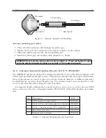
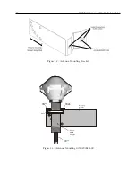
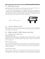
Arbiter also sells an external surge arrester for additional protection. Figure 4.4 illustrates the
GNSS surge arrester kit (P/N AS0094500), which is mounted in line with the antenna cable. The
surge suppressor has two female F connectors, which are bidirectional, and two mounting holes and
a ground attachment point. It comes with hardware for connecting to a solid ground. The surge
arrester passes power to the GNSS antenna, but does not draw power.
Figure 4.4: GNSS Surge Arrester
Antenna
Receiver
Surge Arrester/Grounding Block
AS0094500A
4.3.1
Using the GNSS Surge Arrester
Before installation, review the documentation on this device found in Appendix A. The AS0094500
surge arrester is weatherproof except for the F connectors, which may be sealed with rubber port
seals or GE Silicone II compound.
4.4
Technical Details of GNSS Antennas and Cables
4.4.1
Length and Loss Considerations
Standard Antenna Cable
The standard antenna cable assembly included with the clock is constructed using a 15 m (50 ft)
length of RG-6 type low-loss coaxial cable, terminated with male Type F connectors. Optional
lengths of RG-6 coax are separately available for longer runs; see Table 4.2, Cable Data and
Accessory Information.
Effects of Cable Parameters
To receive GNSS signals and properly operate the clock, the type and length of the cable are
important. Due to their effect on specific parameters described in the following paragraphs, any
changes to the length and/or type of antenna cable should be made carefully. Damaged cables may
also affect performance.
Cable and Antenna Delay
Two factors must be compensated for to assure the best accuracy from the clock, cable delay and
antenna group delay. Together they are called System Delay. These two values are added together
and configured in the clock. Firmware uses these values to counteract the effect that the combined
Summary of Contents for 1201B
Page 4: ...iv ...
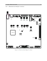
Page 153: ...B 7 Four Fiber Optic Outputs 135 Figure B 4 Jumper Locations ...