116
Technical Specifications and Operating Parameters
12.1.3
Power Supply
All clock models may be fit with either one or two power supplies that provide 24 Vdc to the clock. Power
supply options include either Universal (86 V
ac
to 265 V
ac
, 40 Hz to 440 Hz, 110 V
dc
to 370 V
dc
), or Low
DC Only (22 V
dc
to 67 V
dc
). Each supply comes with a surge withstand protect circuit at the supply inlet to
guard the supply against sudden overvoltage conditions. A surge protector will normally flatten the voltage
but may take out the supply fuse. Inlet supplies are connected in parallel to the main board and separated
by diodes.
12.1.4
Network Section
With Option 34 installed, the network section provides a communication path to the clock that can be
secured first by authenticating with user credentials. It provides NTP and PTP (IEEE 1588v2) outputs and
may be managed using SNMP. While the network section runs on it’s own, it connects to the clock system
providing system information as well as receiving the important PPS timing from the clock to produce
accurate NTP and PTP signals.
12.1.5
Legacy Section
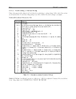
The legacy section supplies all the standard inputs and outputs, like IRIG-B, pulses, event capturing, serial
communications and relay contacts. The usual backbone of legacy timing is IRIG-B, which the legacy section
supplies on six separate and independent outputs on the large connector block. Each output driving up to 75
mA at TTL/CMOS levels, there is ample drive power for numerous relays and other IEDs. Note that each
of the three TTL/CMOS outputs are individually configurable, with two independent instances of IRIG-B.
There are two serial outputs, with two RS-232 serial ports, and one RS-485 embedded in COM1.
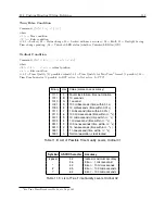
One set of multipurpose, single-pole, double-throw mechanical contacts are available for signaling an
alarm, or providing a timed contact based on the programmable pulse feature. Alarms consist of out of
lock (with the GNSS), alarm (external interference, spoofing, etc.), fault (hardware problem), and a clock
stabilized indication. Contacts are labeled as normally open (NO), normally closed (NC) and common
(COM). The term “normally” refers to the relay condition when the clock is powered off, which serves as a
failsafe indication.
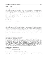
Other standard functions available include modulated IRIG-B and one fiber optic output for digital
timing purposes.
12.1.6
Option Connectors
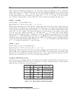
There are nine available option boards that may be added, that provide different input/output functions.
For more detail, see the option list in Section 2.3.8 and in Appendix B.
12.2
GNSS Receiver Characteristics
12.2.1
Input Signal
GPS L1 C/A code, GLONASS CT code, GALILEO/COMPASS L1 OS Data + Pilot
12.2.2
Timing Accuracy
Specifications apply at the unmodulated IRIG-B, 1 PPS and Programmable Pulse outputs when receiving
4 or more satellites
±
100 ns peak
Summary of Contents for 1201B
Page 4: ...iv ...
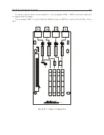
Page 153: ...B 7 Four Fiber Optic Outputs 135 Figure B 4 Jumper Locations ...


