2. Protects connected equipment from the damaging effects of elec-
trical events.
3. Passes DC needed to energize the GNSS antenna.
7.2.3
Installation
Mounting Location
Mount as close as possible to a good earth ground. The shorter the
path between the arrester and the earth ground, the more effectively
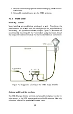
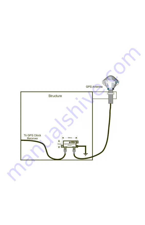
and reliably it will bypass the induced voltages. Figure 7.2 illustrates the
recommended mounting with the F-connectors facing downward. Install
drip loops in the cables to reduce the likelihood of moisture penetration.
Figure 7.2: Suggested Mounting of the GNSS Surge Arrester
Antenna and Clock Connections
The GNSS Surge Arrester terminal are labeled to indicate which termi-
nals connect to the GPS receiver and to the GNSS antenna. Use only
a low-loss, tri-shield or quad-shield coaxial cable.
68

