


12
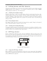
Connecting Inlet Power, Input and Output Signals
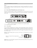
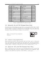
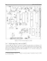
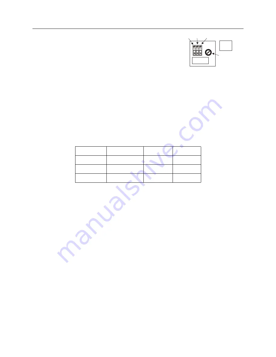
Figure 3.3: Option 10 Power Supply Inlet
Description
G – +
FUSE 1AF/250V
110 – 350 Vdc
85 – 250 RMS
47 – 440 Hz
<20W Typ.
Ground Negative Positive Label
Fuse
3.3.1
Option 10, Connecting Inlet Power
When wiring this power supply, make sure to first connect an earth ground wire to the terminal
strip connector labeled “G” (for ground). After connecting a ground wire, connect the positive and
negative leads from the station batteries to the corresponding Option 10 terminals. Positive and
negative terminals are marked on the terminals as “+” and “–”.
3.4
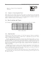
Fuse Locations and Types
Use the fusing table below for identifying the correct fuse for your option power supply.
PS Option
Arbiter P/N
Fuse ID
Size, mm
07
FU0001816
F1AL250V
5 x 20
08
FU0001419
T2AL250V
5 x 20
10
FU0001816
F1AL250V
5 x 20
Table 3.2: Fuse Chart
3.4.1
Replacing Fuses
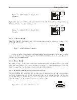
An IEC-320 power inlet connector includes a 1-A, 250-V fast acting fuse. The fuse is contained in
a small compartment with a snap-fit latch, which also has a compartment for a spare fuse. Check
Table 3.2 for replacement fuse information.
The fuse compartment is located directly adjacent to the input connector socket, and can be
opened by pulling both sides directly out away from the chassis, or by gently prying with a small
flag-blade screwdriver. To replace the fuse, first disconnect the line cord from the power source and
then remove the cord from the rear-panel IEC connector. The in-circuit fuse is the innermost one;
inspect it to determine if it is open. As required, replace with fuse in the outer compartment, and
replace the spent fuse.
Option 08 and 10 fuses are located in a separate threaded compartment. To check the fuse, use
a small flat-bladed screwdriver and turn the cover counter-clockwise. The cover and fuse should
pop out. CAUTION: Replace fuse only with another of the same type and rating. See Table 3.2
above for the correct fuse configured for your option.
To replace the fuse, first disconnect inlet power from the clock. Using a small flat-blade screw-
driver, turn the fuse cover counter-clockwise (CCW) and it should pop outward. Replace fuse with
the same size and type.
Summary of Contents for 1092A
Page 4: ...iv ...
Page 18: ...xviii LIST OF TABLES ...
Page 129: ...C 10 Option 20A Four Fiber Optic Outputs 111 Figure C 7 Option 20A Jumper Locations ...
Page 131: ...C 11 Option 27 8 Channel High Drive 113 Figure C 8 Option 27 Jumper Locations ...
Page 148: ...130 Options List Figure C 10 Option 29 Connector Signal Locations ...