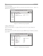
C.15 Option 34: NTP/PTP Server
163
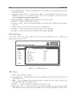
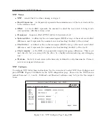
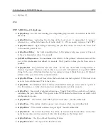
NTP Terms
•
NTP
– reveals that it is either running or stopped.
•
Root Dispersion
– (or dispersion) represents the maximum error of the local clock relative
to the reference clock.
•
Offset
– (or clock offset) represents the amount to adjust the local clock to bring it into
correspondence with the reference clock.
•
Frequency
– frequency offset (PPM) relative to hardware clock.
•
System Jitter
– is defined as the root-mean-square (RMS) average of the most recent offset
differences, and it represents the nominal error in estimating the offset (of the system).
•
Clock Jitter
– is defined as the root-mean-square (RMS) average of the most recent offset
differences, and it represents the nominal error in estimating the offset (of the clock).
•
Clock wander
– is the RMS of exponentially weighted frequency differences. This is not
used directly, but can, along with the jitter, be a highly useful monitoring and debugging
tool.
•
Stratum
– the level of each server in the hierarchy is defined by a stratum number. Primary
servers are assigned stratum one.
NTP Configure
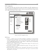
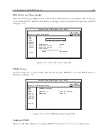
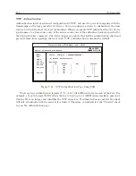
To configure NTP follow these instructions. Use the cursor keys to select NTP, then Configure and
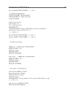
press ENTER. Figure C.40 illustrates the NTP configuration page. Choices for the NTP Version
include Versions 1, 2, 3 and 4. Multicast and Broadcast addresses may be typed in the assigned
boxes.
Status [ Configure ] Authentication
NTP Version [4]
Multicast Address [ ]
Broadcast Address
Ethernet Port 1 [ ]
Ethernet Port 2 [ ]
Apply Reset
ARBITER
SYSTEMS
Option 34 Network Time Module
[NTP]
PTP
SNMP
Clock
Network
System
Support
Logout
Computer Name (or IP address) – ssh – 80x24
Figure C.40: NTP Configure Page Using SSH
Summary of Contents for 1092A
Page 4: ...iv ...
Page 18: ...xviii LIST OF TABLES ...
Page 129: ...C 10 Option 20A Four Fiber Optic Outputs 111 Figure C 7 Option 20A Jumper Locations ...
Page 131: ...C 11 Option 27 8 Channel High Drive 113 Figure C 8 Option 27 Jumper Locations ...
Page 148: ...130 Options List Figure C 10 Option 29 Connector Signal Locations ...

