


C.4 Option 03: Four Additional Outputs –
Obsoleted by Opt36
101
WARNING
Do not remove the top cover while power is applied. Hazardous voltages are present
while the power cord is connected. Always disconnect the unit from the input power source before
removal of the top cover.
General Information
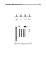
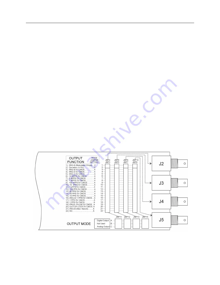
Option 03 incorporates an extremely flexible output selection system using jumpers on the
Option 03 printed circuit board. Each of the four rear-panel BNC-type I/O connectors, included
with Option 03, can be configured to perform any of the available output functions. Figure C.1
shows the locations and functions for all of the jumpers on the Option 03 board.
Function Selection
Jumpers JMP3 through JMP10 determine which output function their respective I/O connec-
tors perform. The dotted lines in Figure C.1 show the relationships between the jumper strips
and the connectors. Set the jumper for each connector to the appropriate location for the type of
output signal desired. Jumpers JMP4, 6, 8 and 10 refer to Output Function selections 1 and 2.
Jumpers JMP3, 5, 7, and 9 refer to Output Function selections 3 through 22. The signals available
are listed in the text to the left of the jumpers in Figure C.1.
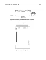
Mode Selection
In addition to specifying the output signal type for each individual connector, it is necessary to
define whether the signal is analog or digital. This is accomplished using jumpers JMP11, JMP12,
JMP14, and JMP15. Each of these jumpers corresponds to the output function jumper for one of
the output connectors; the relationships are illustrated by the dotted lines in Figure C.1. Table C.1
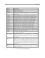
shows the Function and Mode jumper settings for all of the various output signal types. Only the
Modulated IRIG-B and Deviation outputs are analog; all others are digital.
Figure C.1: Option 03 Jumper Configuration
Summary of Contents for 1092A
Page 4: ...iv ...
Page 18: ...xviii LIST OF TABLES ...
Page 129: ...C 10 Option 20A Four Fiber Optic Outputs 111 Figure C 7 Option 20A Jumper Locations ...
Page 131: ...C 11 Option 27 8 Channel High Drive 113 Figure C 8 Option 27 Jumper Locations ...
Page 148: ...130 Options List Figure C 10 Option 29 Connector Signal Locations ...