42
The Setup Menus
6.7
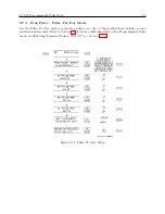
Set Programmable Pulse Mode
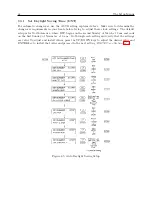
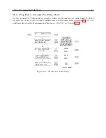
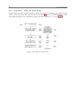
Use the “Set Prog. Pulse” menu to set up one of the many pulse modes available for broadcasting
a pulse from J2
−
J5 (see Table 5.2 and Figure 5.1) at a predetermined interval or rate. Also,
there is a “pulse-per-day” mode and a “pulse-per-year” mode. Programming includes adjusting the
pulse width, from a minimum of 10 milliseconds to 600 seconds, depending on the application, and
configuring the pulse to occur at either UTC or Local time.
RS-232C: see Section 9.2.10
Figure 6.9: Programmable Pulse Setup
6.7.1
Entering Numerical Values
When installing numerical values first use the UP/DOWN keys to change the digits and then the
SETUP and ENTER to move the cursor left or right. Then, use the UP/DOWN keys as before
to change digits. To complete the installation after you have configured the numerical value, press
the ENTER key repeatedly to move the cursor to the right and exit the menu.
Summary of Contents for 1088A
Page 4: ...iv ...
Page 6: ...vi ...
Page 18: ...xviii LIST OF FIGURES ...
Page 23: ...1 4 Attaching Rack Mount Ears to 1088A B Series Clocks 3 Figure 1 2 Attaching Rack Mount Ears ...
Page 24: ...4 Unpacking the Clock ...
Page 32: ...12 Front and Rear Panels ...
Page 38: ...18 Connecting Inlet Power Input and Output Signals ...
Page 46: ...26 GPS Antenna and Cable Information ...
Page 48: ...28 Setting Internal Jumpers Figure 5 1 Model 1088B Main Board ...
Page 76: ...56 The Setup Menus ...
Page 112: ...92 Serial Communication and Command Set ...
Page 127: ...B 4 Physical Dimensions 107 Figure B 1 Suggested Mounting of the AS0094500 Surge Arrester ...
Page 128: ...108 Using Surge Arresters ...
Page 145: ...C 5 Option 04 Parallel BCD Output 125 Figure C 4 Option 04 Output Jumper Settings ...
Page 146: ...126 Options List Figure C 5 Option 04 Board Layout and Jumper Locations ...
Page 166: ...146 Options List Figure C 12 Option 17 Board Layout and Jumper Locations ...
Page 187: ...C 16 Option 20A Four Fiber Optic Outputs 167 Figure C 22 Option 20A Jumper Locations ...
Page 194: ...174 Options List Figure C 24 Option 23 Internal Jumper Setup ...
Page 196: ...176 Options List Figure C 25 Option 27 Jumper Locations ...
Page 214: ...194 Options List Figure C 28 Option 29 Connector Signal Locations ...
Page 270: ...250 Options List ...


