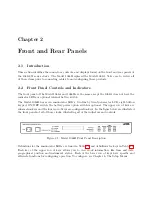
2.2 Front Panel Controls and Indicators
7
•
ON LINE
: Indicates the active clock, especially when using the Option 18, Redundant
Interface, when two clocks are interconnected.
•
OUT OF LOCK
: Illuminates when the clock has not yet synchronized, or has lost synchro-
nization, with the GPS.
•
FAULT
: Indicates when a GPS receiver or clock fault occurs. See Table 10.1 for list of fault
conditions.
2.2.3
Command Key Definitions
Table 2.2 subdivides all of the functions of the eight keys by name and function. Some of the keys
have alternate functions as well.
Key
Function
Alternate Function
TIME
time and date
NA
POSITION
view latitude, longitude and
elevation
NA
EVENT or DEVIATION
view event or deviation
NA
STATUS
view clock and receiver status
NA
SETUP
enter setup mode
move cursor left in data entry
mode
UP
select upper value
increase numerical value
DOWN
select lower value
decrease numerical value
ENTER
install selected value
move cursor right in data en-
try mode
Table 2.2: Command Key Definitions
2.2.4
LCD Display
The Model 1088A/B series clocks contain a liquid crystal display (LCD), which provides a
20-character by 2-line readout.
The readout displays instrument status, time, position and
event/deviation data. The readout is also used to display the current configuration of operation
parameters.
2.2.5
Front Panel Keys
View various functions using the four upper keys, and configure of operational parameters using
the four lower keys on the front panel. However, using an RS-232 command, you can control the
operation of the keypad and display (lock, enable, blank). Refer to Section 9.2.5, in the Serial
Communication and Command Set, for a detailed description of RS-232 commands to control the
front panel. The front-panel pushbutton keys are described below.
Summary of Contents for 1088A
Page 4: ...iv ...
Page 6: ...vi ...
Page 18: ...xviii LIST OF FIGURES ...
Page 23: ...1 4 Attaching Rack Mount Ears to 1088A B Series Clocks 3 Figure 1 2 Attaching Rack Mount Ears ...
Page 24: ...4 Unpacking the Clock ...
Page 32: ...12 Front and Rear Panels ...
Page 38: ...18 Connecting Inlet Power Input and Output Signals ...
Page 46: ...26 GPS Antenna and Cable Information ...
Page 48: ...28 Setting Internal Jumpers Figure 5 1 Model 1088B Main Board ...
Page 76: ...56 The Setup Menus ...
Page 112: ...92 Serial Communication and Command Set ...
Page 127: ...B 4 Physical Dimensions 107 Figure B 1 Suggested Mounting of the AS0094500 Surge Arrester ...
Page 128: ...108 Using Surge Arresters ...
Page 145: ...C 5 Option 04 Parallel BCD Output 125 Figure C 4 Option 04 Output Jumper Settings ...
Page 146: ...126 Options List Figure C 5 Option 04 Board Layout and Jumper Locations ...
Page 166: ...146 Options List Figure C 12 Option 17 Board Layout and Jumper Locations ...
Page 187: ...C 16 Option 20A Four Fiber Optic Outputs 167 Figure C 22 Option 20A Jumper Locations ...
Page 194: ...174 Options List Figure C 24 Option 23 Internal Jumper Setup ...
Page 196: ...176 Options List Figure C 25 Option 27 Jumper Locations ...
Page 214: ...194 Options List Figure C 28 Option 29 Connector Signal Locations ...
Page 270: ...250 Options List ...


