6
Front and Rear Panels
2.2.1
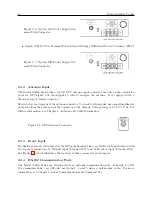
Annunciator LED Definitions
Annunciator LED
Color
Purpose
Operate
Green
Clock Operating
Charge*
Green
Illuminates when the charging circuit for
the internal battery is in the high charge
mode.
In Use*
Green
Illuminates when the power is supplied by
backup battery.
Lo Battery*
Red
Illuminates when the battery voltage falls
below 5.6 volts.
On Line
Green
Indicates Active Clock**
Unlocked
Red
Out-of-Lock when ON
Fault
Red
Internal/External Faults***
Table 2.1: Annunciator LED Definitions
* Only active with clock power backup battery. Refer to the option information sheet for details
about the internal battery operation.
** When used with Option 18, Redundant Interface, the On Line LED indicates which of the two
interconnected clocks is active.
*** Illuminates when a fault condition exists with the clock or GPS receiver. See Section 10.3.
2.2.2
LED Status Indicators
Four LED’s provide information about the operational status of the instrument. The Operate and
On Line LEDs are green and the Out-of-Lock and Fault LEDs are red. For normal operation, with
the clock locked and accurate, the two green LEDs should be ON and the two red LEDs should be
OFF.
Three LED’s provide information about the clock power backup battery. The Charge and In Use
LEDs are green and the Lo Battery LED is red.
The following definitions apply to these indicators:
•
OPERATE
: Indicates that power is being supplied to the clock.
•
CHARGE
: Indicates that the charging circuit for the internal battery is in the high charge
mode. Whenever power is present at the rear-panel power inlet, the charging circuit will
provide a trickle charge. If the battery charge level falls below a preset threshold, the high
charge mode will be activated.
•
IN USE
: Indicates that the internal battery is supplying power to the clock.
•
LO BATTERY
: Indicates the backup battery voltage falls below 5.6 volts.
Summary of Contents for 1088A
Page 4: ...iv ...
Page 6: ...vi ...
Page 18: ...xviii LIST OF FIGURES ...
Page 23: ...1 4 Attaching Rack Mount Ears to 1088A B Series Clocks 3 Figure 1 2 Attaching Rack Mount Ears ...
Page 24: ...4 Unpacking the Clock ...
Page 32: ...12 Front and Rear Panels ...
Page 38: ...18 Connecting Inlet Power Input and Output Signals ...
Page 46: ...26 GPS Antenna and Cable Information ...
Page 48: ...28 Setting Internal Jumpers Figure 5 1 Model 1088B Main Board ...
Page 76: ...56 The Setup Menus ...
Page 112: ...92 Serial Communication and Command Set ...
Page 127: ...B 4 Physical Dimensions 107 Figure B 1 Suggested Mounting of the AS0094500 Surge Arrester ...
Page 128: ...108 Using Surge Arresters ...
Page 145: ...C 5 Option 04 Parallel BCD Output 125 Figure C 4 Option 04 Output Jumper Settings ...
Page 146: ...126 Options List Figure C 5 Option 04 Board Layout and Jumper Locations ...
Page 166: ...146 Options List Figure C 12 Option 17 Board Layout and Jumper Locations ...
Page 187: ...C 16 Option 20A Four Fiber Optic Outputs 167 Figure C 22 Option 20A Jumper Locations ...
Page 194: ...174 Options List Figure C 24 Option 23 Internal Jumper Setup ...
Page 196: ...176 Options List Figure C 25 Option 27 Jumper Locations ...
Page 214: ...194 Options List Figure C 28 Option 29 Connector Signal Locations ...
Page 270: ...250 Options List ...


