222
Options List
C.22.4
SSH Console Interface
These instructions cover the setup and maintenance of the 1088A/B using the Secure Shell (SSH)
Console Interface. Secure Shell is an alternative to using the Telnet protocol, and used for securely
gaining access to a remote system like the optional Option 34. Configure all settings through one
of the Ethernet ports. Instructions on using the Web Interface for the same purpose are found in
Section C.22.3.
Any Secure Shell (SSH) client, like OpenSSH or PuTTY
TM
, is suggested. Make sure to select
SSH and type in the device’s IP address and connect. For Mac users, Terminal works fine. At the
command prompt (
B
is the command prompt) type:
B
ssh clockoption@
host
where
host
is
either the hostname (if served by your DNS server) or the IP address.
Press ENTER after typing the IP address. Shortly, you should be prompted for the password.
Type in the password and press ENTER. The console interface should open and appear similar to
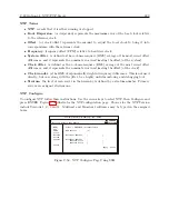
Figure C.49.
Startup Page: System Status
When logging in to the Option 34 using SSH console the opening screen should be the System
Status information page. This provides an overview of the operation of the Option 34. Figure C.49
illustrates the opening page.
Status| [Configure] | Password | Update | Reboot
System Time : 11:24:17 04/19/2011
System Time Offset : -114us
Time Quality : Locked
NTP : Running
PTP : Enabled (Running)
SNMP : Enabled (Running)
SNMP Traps : Enabled
Temperature : 33.3C
ARBITER
SYSTEMS
Option 34 Network Time Module
NTP
PTP
SNMP
Clock
Network
[System]
Support
Logout
Computer Name (or IP address) – ssh – 80x24
Figure C.49: SSH Console Interface: Startup Screen
If you do not know the IP address of the port you are connected to, press the SYSTEM key
on the front panel several times until you reach
OPTION STATUS
and press the ENTER. Press the
UP or DOWN keys to scroll through the Option 34 pages. Messages should appear separately for
NET1 (port 1) and for NET2 (port 2). If the IP addresses do not appear, then check to make sure
a network cable is connected between the chosen port and an active network. If there is no DHCP
server on the network, a port set for DHCP will not display. Factory default settings include Port
1 set with a static IP address – 192.168.0.232. Make sure that the Link LED is lit.
IP addresses for all Ethernet ports of the installed Option 34 are either set automatically by the
Dynamic Host Configuration Protocol (DHCP) server on your network, or set to a static address.
The front panel will indicate the IP address of each port, if there is a connected cable.
Summary of Contents for 1088A
Page 4: ...iv ...
Page 6: ...vi ...
Page 18: ...xviii LIST OF FIGURES ...
Page 23: ...1 4 Attaching Rack Mount Ears to 1088A B Series Clocks 3 Figure 1 2 Attaching Rack Mount Ears ...
Page 24: ...4 Unpacking the Clock ...
Page 32: ...12 Front and Rear Panels ...
Page 38: ...18 Connecting Inlet Power Input and Output Signals ...
Page 46: ...26 GPS Antenna and Cable Information ...
Page 48: ...28 Setting Internal Jumpers Figure 5 1 Model 1088B Main Board ...
Page 76: ...56 The Setup Menus ...
Page 112: ...92 Serial Communication and Command Set ...
Page 127: ...B 4 Physical Dimensions 107 Figure B 1 Suggested Mounting of the AS0094500 Surge Arrester ...
Page 128: ...108 Using Surge Arresters ...
Page 145: ...C 5 Option 04 Parallel BCD Output 125 Figure C 4 Option 04 Output Jumper Settings ...
Page 146: ...126 Options List Figure C 5 Option 04 Board Layout and Jumper Locations ...
Page 166: ...146 Options List Figure C 12 Option 17 Board Layout and Jumper Locations ...
Page 187: ...C 16 Option 20A Four Fiber Optic Outputs 167 Figure C 22 Option 20A Jumper Locations ...
Page 194: ...174 Options List Figure C 24 Option 23 Internal Jumper Setup ...
Page 196: ...176 Options List Figure C 25 Option 27 Jumper Locations ...
Page 214: ...194 Options List Figure C 28 Option 29 Connector Signal Locations ...
Page 270: ...250 Options List ...


