C.3 Option 02: GPS Battery Backup -
Obsolete
111
C.3
Option 02: GPS Battery Backup -
Obsolete
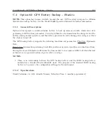
NOTE:
This option has become obsolete because the new GPS receivers incorporate a lithium
dioxide data backup battery. See the Model 1088B Operation Manual for further information.
C.3.1
General Description
Option 02 incorporates a nickel-cadmium battery to back up memory circuits, which store data
pertaining to GPS system parameters. Circuitry within the clock maintains the charge level of the
battery during normal operation, and the battery preserves the data during power outages or when
the clock is turned off.
The GPS backup battery supports the following functions and parameters: Function: Ephemeris
Data;
Description: Information pertaining to satellite position or projected position, as a function of time.
Storing the above information will reduce the time needed to re-acquire satellite lock when the unit
is turned on, or upon restoration of power after an outage.
NOTES:
1. There is no relationship between the GPS backup battery and the RAM backup battery
included in a standard Model 1088A/B clock. The purpose of the standard RAM backup
battery is to preserve the configuration settings for the instrument.
C.3.2
Specifications
Nickel-Cadmium, 3.6 volts, 60mAh, Memory Retention Time: 2 months (approximate)
Summary of Contents for 1088A
Page 4: ...iv ...
Page 6: ...vi ...
Page 18: ...xviii LIST OF FIGURES ...
Page 23: ...1 4 Attaching Rack Mount Ears to 1088A B Series Clocks 3 Figure 1 2 Attaching Rack Mount Ears ...
Page 24: ...4 Unpacking the Clock ...
Page 32: ...12 Front and Rear Panels ...
Page 38: ...18 Connecting Inlet Power Input and Output Signals ...
Page 46: ...26 GPS Antenna and Cable Information ...
Page 48: ...28 Setting Internal Jumpers Figure 5 1 Model 1088B Main Board ...
Page 76: ...56 The Setup Menus ...
Page 112: ...92 Serial Communication and Command Set ...
Page 127: ...B 4 Physical Dimensions 107 Figure B 1 Suggested Mounting of the AS0094500 Surge Arrester ...
Page 128: ...108 Using Surge Arresters ...
Page 145: ...C 5 Option 04 Parallel BCD Output 125 Figure C 4 Option 04 Output Jumper Settings ...
Page 146: ...126 Options List Figure C 5 Option 04 Board Layout and Jumper Locations ...
Page 166: ...146 Options List Figure C 12 Option 17 Board Layout and Jumper Locations ...
Page 187: ...C 16 Option 20A Four Fiber Optic Outputs 167 Figure C 22 Option 20A Jumper Locations ...
Page 194: ...174 Options List Figure C 24 Option 23 Internal Jumper Setup ...
Page 196: ...176 Options List Figure C 25 Option 27 Jumper Locations ...
Page 214: ...194 Options List Figure C 28 Option 29 Connector Signal Locations ...
Page 270: ...250 Options List ...


