C.15 Option 27: 8-Channel High Drive
155
C.15.6
Output Loading (Modulated IRIG-B)
Driving modulated IRIG-B loads is simpler than for unmodulated IRIG-B loads because input
impedances are substantially greater (several kilohms typically); and most modulated IRIG-B
loads include some sort of leveling or AGC amplifier, providing tolerance for signal level variations.
Consequently, modulated IRIG-B loads may be connected with greater ease; Arbiter Systems rec-
ommends that your simply calculate the effective parallel load impedance of the parallel-connected
loads. As long as the load impedance is 50 ohms or more per driver, and the loads will accept a
3 Vpp minimum signal level, and the connecting lines are short (5 ohms or less loop resistance),
then no further analysis is required.
As with unmodulated signals, two or more drivers may be paralleled if desired. Unlike the
current-limited unmodulated IRIG-B drivers, the modulated IRIG-B drivers are impedance-limited
and will operate properly into any load impedance, including a short circuit.
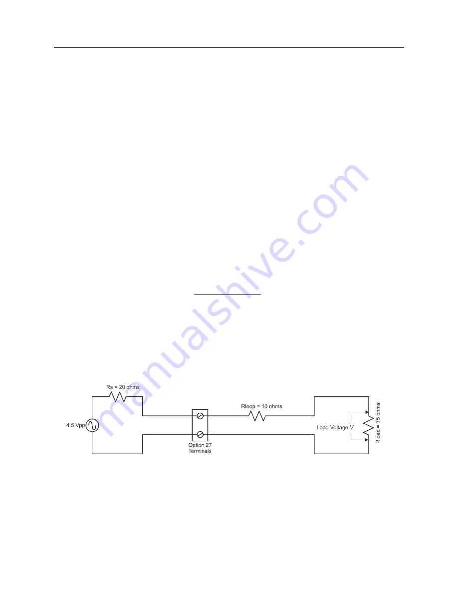
If the loop resistance is greater than 5 ohms, then it may be treated as additional source
resistance in series with the 20-ohm driver impedance. This source resistance then forms a voltage
divider with the load. See calculation for “Output Level at Load” below by using Equation C.1.
For Example (see figure below)
Using Equation C.1 to calculate the Output Level at Load;
(C.1)
V
=
R
load
R
S
+
R
loop
+
R
load
×
4
.
5
Source impedance of driver: 20 ohms
Loop Resistance: 10 ohms
Load Resistance: 75 ohms
Output Level at Load
V
= (75
÷
105)
×
4
.
5 = 3
.
2
V pp
Summary of Contents for 1084A
Page 4: ...iv ...
Page 6: ...vi ...
Page 18: ...xviii LIST OF FIGURES ...
Page 24: ...4 Unpacking the Clock ...
Page 36: ...16 Connecting Inlet Power Input and Output Signals ...
Page 44: ...24 GPS Antenna and Cable Information ...
Page 114: ...94 Startup and Basic Operation ...
Page 123: ...B 4 Physical Dimensions 103 Figure B 1 Suggested Mounting of the AS0094500 Surge Arrester ...
Page 124: ...104 Using Surge Arresters ...
Page 134: ...114 Options List C 6 2 Option 06 Firmware Setup Figure C 3 Option 06 Firmware Setup ...
Page 142: ...122 Options List Figure C 5 Option 06 Output Jumper Settings ...
Page 158: ...138 Options List Figure C 13 Option 17 Board Layout and Jumper Locations ...
Page 163: ...C 13 Option 20A Four Fiber Optic Outputs 143 Figure C 14 Option 20A Jumper Locations ...
Page 170: ...150 Options List Figure C 16 Option 23 Internal Jumper Setup ...
Page 172: ...152 Options List Figure C 17 Option 27 Jumper Locations ...
Page 190: ...170 Options List Figure C 20 Option 29 Connector Signal Locations ...
Page 246: ...226 Options List ...


