10
3.4
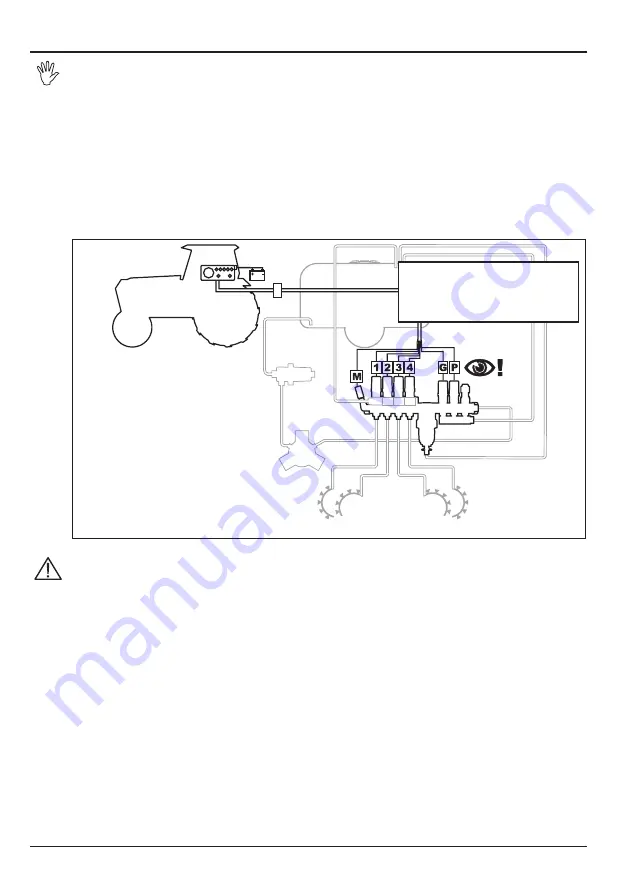
Connection to control devices
• The diagram below is for illustrative purposes only; to ensure correct operation,
always refer to the installation manual relevant to the control device you are using.
• Connections and setting into operation are best left to qualified personnel.
ARAG disclaims all liabilities for damage to equipment, persons or animals resulting
from wrong or improper connection of the unit.
• Any damage to the unit resulting from the above will automatically invalidate any
warranty rights.
Proportional control units are designed for connection to ARAG control units (computers, monitors,
displays).
Each control device comes complete with the necessary connection cables and all cables are mar-
ked for ease of identification; please see Fig. 5 for a description of cable marks and their meanings.
Fig. 5
• Use only the cables supplied with ARAG computers or control boxes.
• Do not pull on the cables. Be careful not to break, tear or shear the cables.
• Check wiring and cables for damage from time to time.
Minimum required cross-section area for cables connected to main control valve is
1.5 mm
2
; minimum required cross-section area for cables connected to remaining unit
components is 0,75 mm
2
.
• Any damage resulting from use of unsuitable cables or anyway other than ARAG
cables will automatically invalidate any warranty rights.
• ARAG disclaims all liabilities for damage to equipment, persons, animals or things
resulting from the above.
M
Pressure transducer
1÷4
Boom section valves
P
Proportional valve
G
Discharge valve
P
Proportional valve with
YELLOW or GREY collar
G
Discharge valve with
RED or LIGHT BLUE collar


