


AS 2.0 D24
18
A maximum of 10 basic modules may be supplied with 24 V DC via the T-bus
connectors.
For more than that, the supply voltage must be connected again via terminals
A1/A2. If the product's connectors are not coded, there is not enough protection
against mixing up the connectors.
4.3.4
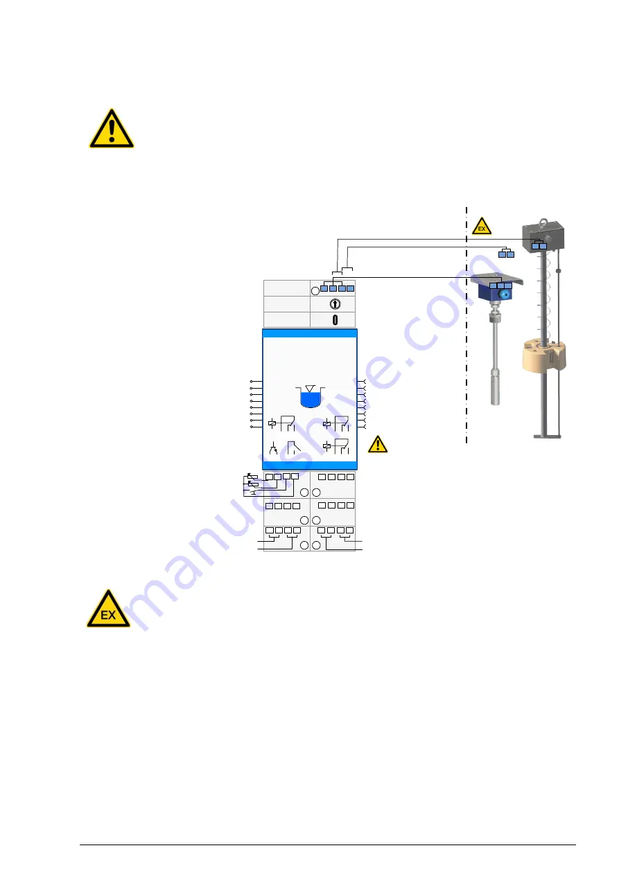
Electrical connection diagram
AS2.0 D24
Safety liquid switch device
A
B
D
C-
A
A1+ A2-
RS485 A
RS485 B
24
22
21
14
12
11
4
3
2
1
230 VAC 1A
Power supply 24VDC, A1+ / A2-
Sensor connection
B/C: LS11/13/21, LW9/VE9
C/D: Namur-Sensor
A/B/C: AF1*/6/21/23/26/33/35/42
Acknowledgment HL alarm
Acknowledgment, i24VDC
Collective alarm fault +24VDC
Power supply -24VDC
HL alarm OC delayed output
Relay 1.1 HL-Alarm output
Relay 3 HL alarm output can
be acknowledged for horn
Sensor sensitivity
Alarm OC time delay
C
B
A
32
34
Relay fault message output
Relay 1.2 HL-Alarm output
-
-
RS485
41
6
5
42
31
B+
com
-
USB-C
-
+
sensor selector switch
Power 24VDC
24
22
21
T-BUS
Plug socket
1 2 3
4 5 6
7 8
RS485 C
Safe area Hazardous area
+
-
Relay de-energized
in alarm condition
230 VAC 1A
230 VAC 1A
1
2
3
4
5
6
20
34
32
31
14
12
11
42
41
6
5
Figure 9 Connection diagram for the AS2.0 D24 G
The control device relay outputs are galvanically isolated and currentless. The
currentless state or alarm state are the same (relay de-energised).