background image


OWNER’S MANUAL


S200TUr Turbidimeter 


AQUALABO 
90 Rue du Professeur Paul Milliez 
94506 Champigny-sur-Marne 
 
Tel.: 

+33(0)155091010 

E-mail:   

[email protected]


Internet:   www.aqualabo.fr 
 
Subject to technical changes. Errors and omissions excepted. 

Summary of Contents for PONSEL Supratec S200TUr

Page 1: ...S200TUr Turbidimeter AQUALABO 90 Rue du Professeur Paul Milliez 94506 Champigny sur Marne Tel 33 0 155091010 E mail info aqualabo fr Internet www aqualabo fr Subject to technical changes Errors and omissions excepted ...

Page 2: ... Connections 7 3 3 1 Power 8 3 3 2 RS 485 8 3 3 3 Relays 8 3 3 4 4 20 mA 8 4 0 Operation 9 4 1 Routine Measurement 9 4 2 Security Access Feature 9 5 0 Instrument Calibration 10 5 1 Calibration Standards 10 5 2 Calibration Procedures 10 5 3 Calibration Error 11 6 0 Instrument Offset 12 6 1 Indexing Calibration Cuvettes 13 6 2 Restoring Factory Settings 13 7 0 Instrument Configuration CONFIG mode 14...

Page 3: ... 7 18 Saving Configuration Settings 21 8 0 Additional Features and Options 22 8 1 Backlit LCD 22 8 2 Ultrasonic Cleaning 22 8 3 RS 485 Output 23 8 3 1 Simple Communication 23 8 3 2 Modbus Communication 24 8 4 Flow Alarm 24 8 5 Flow Controller 24 8 6 Remote Panel Meter 24 9 0 Troubleshooting Maintenance 25 9 1 S200 TUr Fault Detection 25 9 2 System Fail Message 25 9 3 Diagnostic Chart 25 9 4 Techni...

Page 4: ...n Operating Temperature 1 C 50 C 34 F 122 F Wetted Materials Nylon Borosilicate Glass Silicone Polypropylene Stainless Steel Sample Temperature Range 1 C 50 C 34 F 122 F Power Supply 100 240 VAC 47 63 Hz 80VA Insulation Rating Double Insulated Pollution Degree 2 Overvoltage Category II Environmental Conditions Not recommended for outdoor use Altitude up to 2000 meters Up to 95 RH non condensing En...

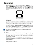
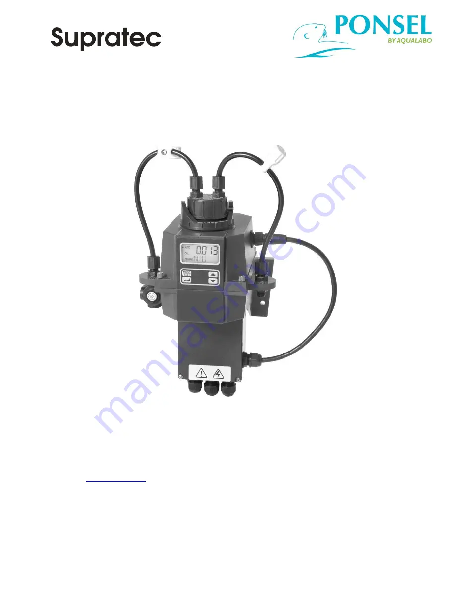
Page 5: ...with fittings for flow through assembly 1 drain vent screw used in pressurized systems 1 Remove the instrument from the packing carton Carefully inspect all items to ensure that no visible damage has occurred during shipment If the items received do not match the order please immediately contact the local distributor or the Supratec Customer Service department 1 2 The Display Figure 1 illustrates ...

Page 6: ...ntinuously The LCD display will show DESC on the lower line in the event that the desiccant pouch needs replacement Replacement desiccant pouches are available from Supratec or the local representative Refer to section 10 2 Replacing or installing the Desiccant Pouch The desiccant can activate an alarm to notify the operator of a saturated desiccant See section 7 15 Desiccant Alarm 2 0 Safety This...

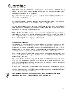
Page 7: ...e to the equipment This symbol identifies important information practices or actions This pictorial alert you to the need read the manual possibly at a different section This pictorial alerts you to electricity electrocution and shock hazards This pictorial is used to indicate useful tips and information ...

Page 8: ...vice and ensure that the front display rests at eye level The overall mounting dimensions of the instrument are shown in Figure 3 The recommended mounting screws are M6 for the instrument enclosure and M4 8 for the field terminal box The S200 TUr is designed to have the field terminal box cradled under the sensor portion of the instrument It is recommended that the field terminal box be mounted fi...

Page 9: ...mum allowable fluid temperature is 50 C 122 F Figure 4 Recommended Plumbing for the Instrument The instrument is equipped to be plumbed using 4 75 mm 3 16 ID 8 mm 5 16 OD flexible tubing Opaque tubing should be used if the tubing will be exposed to sunlight to prevent algae growth In figure 4 there are two flow devices shown The one on the input side is a shutoff clamp used during cuvette maintena...

Page 10: ... are made through the field terminal box which should be located directly under the sensor portion of the instrument The connections are labeled within the terminal box and are self descriptive see Figure 5 Please follow all local and government recommendations and methods for installation of electrical connections to and between the instrument and other peripheral devices Plugs are inserted into ...

Page 11: ...ath this termination 3 3 3 Relays The Alarm 1 and Alarm 2 relays are mechanical relays rated at 240 VAC 2A Please note that the relays are labeled NO Normally Open NC Normally Closed and C Common As these alarms are configured fail safe the normal condition is with power applied to the S200 TUr and in a non alarm condition Operation of these alarms is covered in section 7 5 Configuring the Alarms ...

Page 12: ... of the sample by displaying it on the LCD screen In addition the equivalent signal is provided on the analog 4 20 mA output or the digital output depending on the options selected 4 2 Security Access Feature The instrument is equipped with a security access code feature that can be activated in the configuration mode If the security feature is enabled the screen shown in the illustration below wi...

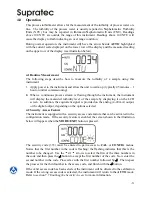
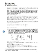
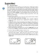
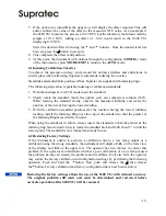
Page 13: ...We recommend that the following materials be used during calibration to achieve the full scale accuracy stated in this manual 1 0 02 NTU Calibration Standard available from Supratec 2 10 0 NTU Calibration Standard available from Supratec 3 100 NTU Calibration Standard available from Supratec 5 2 Calibration Procedures 1 Select the calibration function of the instrument by pressing the MODE EXIT bu...

Page 14: ...life of the desiccant The fan will be turned on during calibration countdowns and after returning to the AUTO mode or after five minutes which ever comes first It is recommended that the measurement chamber be kept covered during the calibration period and that the flow through cuvette be replaced immediately after the calibration to prevent premature saturation of the desiccant 5 3 Calibration Er...

Page 15: ...urbidity using a laboratory turbidimeter contact the Supratec customer services department for examples of laboratory turbidimeters 3 Compare the turbidity reported by the instrument to that obtained in the laboratory If the readings are very close then no offset adjustment or calibration is required and the procedure may be stopped at this step However if the readings are substantially different ...

Page 16: ... the position of the cuvette having the lowest reading 3 With the calibration standard positioned at the location having the lowest turbidity reading install the Indexing Ring over the cap on the standard so that the pointer of the Indexing Ring faces directly forward When using the standards in future always insert the standard so that the pointer of the indexing ring faces forward Slowly rotate ...

Page 17: ...lecting the Output O P The first configuration selection is the O P The selections are 4 20 for the 4 20 mA output 485 for the RS 485 and OFF if no outputs are required Select the desired output by using the and buttons Once the desired output has been set press the button to accept it The next prompts will depend on the output selected 7 2 Setting the 4 20 mA If the 4 20 mA output was turned on p...

Page 18: ...unaffected by any error condition The factory default setting is OFF Select the desired ERLV by using the and buttons then press the button to accept the desired error response 7 4 Configuring the RS 485 Port If the instrument is equipped with this option and the I O selection is changed to 485 prompts will appear for setting the baud rate and the address Select the correct baud rate 1200 2400 480...

Page 19: ... The set point is adjustable to any valid turbidity level over the range of the instrument in steps of 0 01 NTU Alarm Delay Time The alarm delay times are used to prevent ringing of the alarm when the measured turbidity level is close to the set point The function of the delay times is as follows Delay On The turbidity level must exceed the alarm set point continuously for at least this number of ...

Page 20: ...is alarm using the and buttons Once the desired delay time has been set press the button to accept it Delay Off Next the following display will appear to select the number of seconds currently set for the delay off time The current selected number of seconds will be shown Select the desired delay off time for this alarm using the and buttons Once the desired delay time has been set press the butto...

Page 21: ...grouped together to prevent them from being adjusted by accident To gain access to the extended settings select On using the or buttons and press the button 7 9 Speed of Response The speed of response for both displayed and output values of NTU can be adjusted in this menu The default setting is 10 however 100 response speeds are available Although the displayed number is a relative speed the appr...

Page 22: ...LCD Backlight Brightness The LCD backlight brightness may need to be adjusted This is of particular interest if multiple instruments are located in the same area and it is desired for the entire group to have the same appearance Ten levels are available The default brightness is 8 Change the brightness by pressing the or button When the desired brightness has been selected press the button 7 12 Se...

Page 23: ...e S200 TUr indicates that the internal environment is close to the point where humidity could cause condensation the instrument will display DESC as a screen warning If desired a desiccant warning can Activate the alarms relays Can activate an alarm condition on the 4 20mA To activate the alarm relays when the desiccant fails select set one or both alarms to Error see section 7 5 Configuring the A...

Page 24: ...utputs a constant 20 mA while allowing for a small amount of adjustment The adjustment can be made using the and buttons The adjustment limits are 1000 counts or about 1 mA This setting will be slightly different on each instrument as each S200 TUr will be factory set to 20 00mA 7 18 Saving Configuration Settings If extended settings are set to OFF pressing the button will save all settings and th...

Page 25: ...the lower screen Since this is an error condition this may affect the 4 20 mA and alarms depending in the setting of the ERLV 4 20 mA and if an alarm is set up to Error If the correct cuvette is installed and the error is still posted try rotating the flow through unit slightly to improve the connection If this fails to work the cuvette may have to be replaced Catalog 24166S The detection for this...

Page 26: ... basic communications over simple programs such as the Hilgraeve HyperTerminal that is included with most Microsoft Windows packages The user could also use Visual Basic or other programs The default communication parameters are 8 bits no parity and 1 stop bit These can be changed in the Extended CONFIG menus 7 14 RS 485 Parameters The master computer will send out Byte 1 the attention character i...

Page 27: ... both relays to the fail state and setting the 4 20 mA signal to 2 mA There is also a screen indication of the low flow condition and a modbus register is set 8 5 Flow Controller The flow controller limits the flow in high pressure systems to safe flow limits of less than 1 liter minute 8 6 Remote Panel Meter The remote panel meter allows for remote indication of the NTU reading using the 4 20 mA ...

Page 28: ...the flow switch If the S200 TUr is equipped with ultrasonic cleaning an additional message will indicate that the ultrasonic transducer is not making contact or the flow through has been removed CLN If any of these errors occur the instrument will still display readings however the accuracy is not known and the instruments readings may not be reliable A failure is a system fault This is NOT a prob...

Page 29: ... 3 For sever cases of bubbles a stilling chamber is available Call Supratec service department Check flow through cuvette for condensate or leaks Clean cuvette See section 10 1 Recalibrate Refer to section 5 Readings are erratic 1 Bubbles in solution 2 Debris in flow through 1 See above 2 Clean debris from cuvette Readings are lower than expected Instrument out of calibration Recalibrate Refer to ...

Page 30: ... is essential that the enclosure seal on the instrument base be maintained to ensure adequate desiccant life Inspect the seal each time the desiccant pouch is replaced Replace or reseat the seal if it is found to be defective The desiccant should be replaced when the instrument displays DESC A new sealed desiccant pouch and indicator card are available from Supratec To initially install or remove ...

Reviews: