background image

12

Contact Your Sales Representative for Further Assistance.

t

roubleShootinG


(

cont

.)

BEFORE INSPECTION AND /OR SERVICE,

DISCONNECT AND LOCK OUT POWER SOURCE.

WARNING

5.  No Fog

 A.)

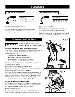
  The self-priming system will usually take about 10 seconds before you see fog output.  


Check to see if the flow control valve is open. The valve is open when the handle is down.

 B.)

  Check the pre-set flow rate valve located inside the tank (refer to page 6 Factory            


Pre-set Flow Valve). Having the pre-set flow rate valve in either a fully closed or fully open  


position will result in no fog output. If the positioning is incorrect, refer to 

page 6

 for    


instructions on calibrating the pre-set flow rate valve.

 C.)

  Check for sediment clogs. Flush the inline strainer and check for sediment build-up    


around the base of the pump. Spray around the pump with a hose and drain the tank.

 D.)

  The pump may not be operating. Check by removing the Inline strainer cap and turning  


system On. If no fluid flows from the strainer, the pump may need to be replaced.

6.  Poor Quality Fog


A.)

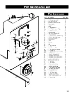
  The liquid feed tube (Part #575) may not be properly positioned. The feed tube is located  


  behind the blade assembly and should be inserted approximately 1/4" into the slot    


between the motor shaft and the stainless steel face plate. Centered in the slot area and  


  aimed slightly downward, free from any rotational contact.


B.)

 Liquid not traveling through the fan blades. This can be diagnosed by viewing the back  


  of a blade assembly during operation (using a bright flashlight). If system is clogged,    


  liquid can be seen spinning out of the slot area between the motor shaft and stainless


  steel face plate (Part #573). If confirmed, replace fan blade assembly (Part #571-assy).


Cleaning the internal passageways of a blade assembly is feasible with the aid of some  

  speciality 

tools. 

7.  Unusual Noise


Squealing at start-up or during operation may be caused by the motor shaft's bearing seal.  


Spray with lubricant at the front of the motor where the shaft exits the motor's frame.

8.  Fan Motor Becomes Excessively Hot


The main fan motor normally becomes very hot to the touch. However, it should not get so  


hot that it begins to smell or smoke, nor should the power cord become hot. Discontinue   


operation and consult an electrician to properly evaluate the problem.

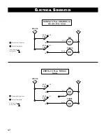
9.  Electrical Breaker Tripping


If the electrical breaker trips off, there is an overload in the system and there may be a      


serious motor problem. Turn off all other devices connected to the same circuit. If the  


breaker continues to trip, the motor is probably in need of repair. Consult an electrician for  

 evaluation.

Summary of Contents for XE CRSM

Page 1: ...derstand Retain for Future Reference XE MOBILE ATOMIZER USER S MANUAL AND OPERATING INSTRUCTIONS OPERATOR S MANUAL NOTICE Rear Feed UL and CSA Electrical Components XE CRSM MODEL 115V 60Hz 1Ph 240V 50...

Page 2: ...INDICATES IMPORTANT INFORMATION THAT IF NOT FOLLOWED MAY CAUSE DAMAGE TO EQUIPMENT WARNING CAUTION NOTICE Notes Description Aquafog CRSM mobile units are intended to condition large volumes of air by...

Page 3: ...EVERallowchildrenin the work area 7 Use of an extension cord for the CRSM is not recommended If necessary refer to the A W G chart in the following section or consult a certified electrician 8 Before...

Page 4: ...G USE OF AN EXTENSION CORD IS NOT RECOMMENDED IF NECESSARY REFER TO FIG 12 NOTICE 4 EXTENSION CORD SPECIFICATIONS FOR SINGLE FAN USE ONLY AWG American Wire Gauge Voltage 25 to 50 ft 50 to 100 ft 115 2...

Page 5: ...ds of time At the base of the plumbing is an in line strainer with a removable cap Occasionally check inside and flush any sediment from the screen The Hose Connection is used to supply fresh water to...

Page 6: ...H The KEY is needed to make changes You will need the KEY located on the side of the electrical control box to make changes see Fig 3 Slide this key on top of the flow valve s stem see Fig 4 to make y...

Page 7: ...ounds of chemical needed per acre B Ounces of chemical per 100 gallons of water applied by conventional spray nozzles If A Convert the pounds into ounces Divide the ounces by 4 36 43 560 sq ft per acr...

Page 8: ...Pivot Fogging Head Up Pivot the fogging head upward into large open air space away from the foliage If greenhouse is equipped with Horizontal Airflow Fans HAF simultaneous operation of CRSM and HAFs...

Page 9: ...ickling out of stationary blade assembly 4 In a small bucket thoroughly pre mix the chemical with some water 5 When Ready Slowly pour the pre mixed chemical into the tank s agitated water 6 Replace th...

Page 10: ...if a film of calcium or mineral deposits is visible on the exterior of the blades Remove any build up from the blades and any debris from blade passageways While cleaning inspect for irregularities o...

Page 11: ...y closed position the automatic priming will not occur resulting in trapped air and poor inconsistent fogging output E Consistency of fogging output greatly depends on the consistency of the cleaning...

Page 12: ...the slot betweenthemotorshaftandthestainlesssteelfaceplate Centeredintheslotareaand aimed slightly downward free from any rotational contact B Liquid not traveling through the fan blades This can be d...

Page 13: ...ST 8 58 5 16 flat washer SST 12 114 Drain fitting nut 1 115 Drain gasket 1 116 5 16 18 finish nut SST 4 117 1 4 20 x 5 8 HH bolt SST 4 308 XE blade tip setscrew SST 3 349 5 16 brass rod 1 391 Top pivo...

Page 14: ...p pivot plate Rear of Housing To Feed Pump 14 16 52 600 L 117 54 20 49 58 56 32 58 57 56 57 116 349 403 391 392 56 394 395 32 479 20 600 R Motor s Junction Box 576 7 523 522 35 To Circulation Pump 434...

Page 15: ...1 84 45 71 C 72 65 295 295 W 14 65 65 84 45 198 67 65 Tank s Wall Inside Tank CRSM Tank Exploded View 232 207 86 423 423 75 171 173 143 3 8 tube fitting provided for optional connection to metering pu...

Page 16: ...oupling 1 111 Axle SST 1 126 1 4 lockwasher SST 4 143 1 4 NPT M x 3 8 tube fitting 1 154 1 4 20 finish nut 4 155 1 4 NPT M x 1 2 compression fitting 1 156 Circulation tube 1 157 8 32 x 3 8 Phillips RH...

Page 17: ...on Denotes Termination Note All green wires go to ground Denotes Line Connection Denotes Termination 240 Volt 1 Phase 50 Hertz Foreign N mtr FAN mtr PUMPS SPST TGS 115 VAC LINE SPST TGS On 2 4 5 1 3 8...

Page 18: ...ck of maintenance or unauthorized repairs or alterations which affect the machine s performance or reliability LIMITATIONS OF LIABILITY TO THE EXTENT ALLOWABLE UNDER APPLICABLE LAW JAYBIRD MANUFACTURI...

Reviews: