10
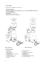
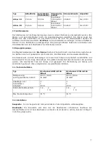
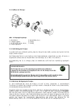
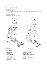
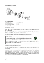
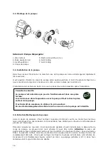
3.3. Exploded parts diagram:
Fig. 3:
Venturi pump
3.4. Mounting the pump
In any case, it must be prevented that the pump runs dry since this would destroy the bearings
after a short period.
The pump head can be fitted into 4 positions of the pump housing. It must be fitted in such a way
that the pressure fitting points to the side, as shown in Fig. 3.
After setting up the pump ensure you can always reach the power plug easily.
3.5. Maintenance / Cleaning of the pump
Depending on contamination, the pump must be cleaned occasionally, at least in two-month
intervals, if necessary more frequently. If the channel in the ceramic axle clogs, the water cooling
is interrupted.
At first, remove pipe connections and undo the bayonet on the pump housing. Now, the impeller
assembly (Fig. 3) can be taken out.
Caution:
This part is tight fit and must be removed carefully
so as not to break the ceramic shaft. It can be cleaned under running water and then re-
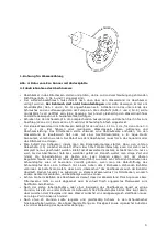
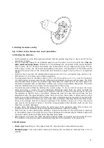
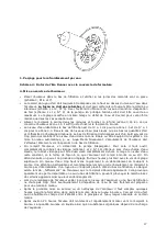
assembled. If the rotor is completely dismounted, also the holes in the cover plate (Fig. 4) have to
be cleaned. They provide for sufficient water cooling of the rotor. The drilling for the water cooling
(Fig. 4, No. 1) in the ceramic axle has always to be free of deposits.
1. Motor housing
2. Air injection nozzle
3. Impeller rotor assembly
4. Pump housing
5. Rubber feet (4 x)
6. O-ring
7. O-ring
Safety advices
The pump is constructed for indoor use only. Before working on the
Aquarium or the pump, the power plug must be disconnected
from the mains.
The connection cable and the power plug must not be changed. If the power cable is
damaged, the pump must be scrapped.


