background image


6

A

B

C

H

D

E

F

SHFWEZ-1 WELL

15.38"          

(39.1)

23.44"                      

(59.5)

13.80"        

(35.10)

12.85"      

(32.6)

14.25"    

(36.2)

22.25"    

(56.5)

5.0"    

(12.7)

Volts

Watts

Amps 1-Phase

Volts

Watts

SHFWEZ-1 WELL 

208/240

1200/1600

5.8 / 6.7

208

1600

G

12.5"                   

(31.8)

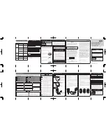
GENERAL SPECIFICATIONS (APW EZFILL HOT FOOD WELLS)

MODEL

OUTSIDE DIMENSIONS

CUT OUT

CONTROL CUT OUT

SHIP WT.

ELECTRICAL SPECIFICATIONS

OPTIONS

24 Lbs. (10.9 Kg)

CLEANING

MODEL

Max Amps 3-Phase

Description: Lever Operated Drain Valve

Amps 1-Phase

Electrical Ratings 1200 EA. @ 208V / 1600 EA. @ 240V

Electrical Ratings 1600 EA. @ 208V

Amps 3-Phase

Stock No.: 56360

Drain Manifold: Fabricated to Unit, Required

  1. Follow General Cleaning Instructions on page 3.

OPERATION

  1. Follow General Operating Instructions on page 3.

n/a

7.7

NOTE: CUT-OUT SIZES ARE DIFFERENT FROM STANDARD APW HFW'S

n/a

APW EZFILL HOT FOOD WELLS                                                                                                                                   

PART NO'S BEGINNING WITH WHFW

INSTALLATION

1.  Follow general installation instructions on 
page 3.                                                               
2.  Make applicable Cut-Out per above table.  
Note: Unit is designed for installation in 
stainless steel tops.  Optional wood mounting 
kit available.                                                       
3.  Apply putty tape to the underside perimeter 
of the well rim outer edge.                                 
4.  Apply a 1/4" (.6) bead of silicone sealant 
adjacent to the putty tape on the well flange.                                                             
5.  Drop well into opening from the top and 
push down until entire parameter of rim is flush 
with the counter surface.
6.  From below the counter surface insert an 8" 
to 10" (20 to 25 cm) flat tip screwdriver into the 
locking ring tab slots and twist in a clockwise 
motion to lock well in place.                                                        
7.  Trim excess putty and sealant from around 
well rim.                                                                  
8.  Mount control to front panel using hardware.  
Maintain 4" (10.2) clearance between well and 
front panel.                                                        
9.  Check nameplate for proper voltage.  
Connect power.                                                                    
10.  Connect overflow tube onhot food well to 
suitable tubing to handle 212 F water.  Run to 
open drain.                                                            

Note: Electrically connect units to comply 
with local and NEC codes.

2.  Main drain is 3/4 female NPT.

1.  Water fill is 3/8 (1.0) tubing connection on left 
back of left controls

Summary of Contents for HOT FOOD WARMER

Page 1: ...16 17 20 21 Exploded View 10 14 18 22 Wiring Diagram 11 15 19 23 Warranty 24 APW Wyott Foodservice Equipment Company 729 Third Avenue Dallas TX 75226 214 421 7366 FAX 214 565 0976 WARNING Improper in...

Page 2: ...to the solenoid and tighten the nut finger tight 6 Using a wrench tighten the nut far enough to crush the sleeve and attach the line NOTE Do not over tighten nut Just enough pressure is required to st...

Page 3: ...t and or thickness of product 4 Keep inset steamtable pan s covered to maintain ideal serving temperature 5 Water is automatically kept at correct level NOTE Turning on any control will activate autof...

Page 4: ...motion to lock well in place 7 Trim excess putty and sealant from around well rim 8 Mount control to front panel using hardware Maintain 4 10 2 clearance between well and front panel 9 Check nameplate...

Page 5: ...motion to lock well in place 7 Trim excess putty and sealant from around well rim 8 Mount control to front panel using hardware Maintain 4 10 2 clearance between well and front panel 9 Check nameplat...

Page 6: ...ons on page 3 2 Make applicable Cut Out per above table Note Unit is designed for installation in stainless steel tops Optional wood mounting kit available 3 Apply putty tape to the underside perimete...

Page 7: ...perimeter of the well rim outer edge 4 Apply a 1 4 6 bead of silicone sealant adjacent to the putty tape on the well flange 5 Drop well into opening from the top and push down until entire parameter...

Page 8: ...8 REPLACEMENT PARTS CATALOG SM50EZ ROUND SOUP WELL DROP IN WITH EZ LOCK SM50EZ P N EZSM50 7D 208 240V 500 660W...

Page 9: ...19 55696 BRACKET ELEMENT HOLDER 20 55695 BRACKET ELEMENT HOLDER 21 89025 10 24 SPEED NUT 22 55992 BOTTOM COVER 23 89059 10 EXTERNAL LOCK WASHER 24 89061 NUT HEX 10 24 25 54544 O RING FOR PROBE HOLDER...

Page 10: ...10 14 17 38 2 15 9 13 11 26 27 31 28 1 16 20 3 5 33 34 30 35 23 24 32 41 24 35 B DETAIL B 29 25 42 43 10 36 23 19 21 22 EZSM50 7D 18 8 37 4 7 39 40 6 12 44 45...

Page 11: ...TING ELEMENT INDICATOR LIGHT AMERICAN PERMANENT WARE INC DALLAS TX 75226 729 THIRD AVENUE SM 50 WIRING DIAGRAM L2 H2 H1 L1 THERMOSTAT L2 H2 H1 L1 RANCO THERMOSTAT ROBERT SHAW HEATING ELEMENT INDICATOR...

Page 12: ...12 REPLACEMENT PARTS CATALOG EZ12D4B SMALL FRAME INSULATED TOP MOUNT EZ FILL HOT FOOD WELLS HFWEZ12D P N EZ12D4B 208 240V 500 660W...

Page 13: ...208 240V 500W 660W 26 55695 BRACKET ELEMENT HOLDER 27 55696 BRACKET ELEMENT HOLDER 28 55992 BOTTOM COVER 29 56404 BOTTOM COVER 30 56655 DRAIN STRAINER 31 88961 10 24 HEX NUT GREEN GROUND 32 89025 10...

Page 14: ...14 C DETAIL C D DETAIL D 10 24 42 6 40 37 41 39 38 14 15 1 8 7 4 49 2 35 26 27 25 28 51 50 29 48 47 11 43 44 30 46 5 31 12 20 32 13 33 34 19 36 19 45 17 23 16 22 18 34 48 50 47 13 9 33 HFWEZ12D 21 3...

Page 15: ...15 HEATING ELEMENT INDICATOR LIGHT AMERICAN PERMANENT WARE INC DALLAS TX 75226 729 THIRD AVENUE HFW 12 WIRING DIAGRAM THERMOSTAT...

Page 16: ...16 REPLACEMENT PARTS CATALOG HFWEZ 1 SMALL FRAME INSULATED TOP MOUNT EZ FILL HOT FOOD WELLS SHFWEZ 1D P N EZ1D2B 208V 1600W SHFWEZ 1D P N EZ1D4B 208 240V 1200 1600W...

Page 17: ...208 240V 1200W 1600W 32 54544 O RING FOR PROBE HOLDER 33 54543 PROBE HOLDER 34 54546 WASHER 20 SS 35 88971 SCREW 8 32 X 1 1 2 SS 36 54548 SPACER PROBE HOLDER 37 56655 DRAIN STRAINER 38 54561 CONTROL B...

Page 18: ...51 42 39 43 41 40 33 32 17 34 36 16 1 23 50 5 2 7 6 24 27 38 26 54 52 3 4 49 47 31 25 29 13 30 11 8 9 19 45 46 37 22 35 14 48 20 15 53 18 10 21 28 21 19 21 23 21 24 8 3 19 9 6 19 7 21 20 B DETAIL B 55...

Page 19: ...19 INDICATOR LIGHT HEATING ELEMENTS THERMOSTAT THERMOSTATIC CONTROL CONFIGURATION COMMON PROBE 7 8 1 2 6 5 4 3 L2 L1 H2 H1 L1 L2 1 2 3 4 8 7 6 5 9 10 PN 67186 REV 11 99...

Page 20: ...2D2B 208V 1600W HFWEZ 2D P N EZ2D4B 208 240V 1200 1600W HFWEZ 3D P N EZ3D2B 208V 1600W HFWEZ 3D P N EZ3D4B 208 240V 1200 1600W HFWEZ 4D P N EZ4D2B 208V 1600W HFWEZ 4D P N EZ4D4B 208 240V 1200 1600W HF...

Page 21: ...OLE COVER 30 54526 2 WELL BOTTOM COVER 54538 3 WELL BOTTOM COVER 54539 4 WELL BOTTOM COVER 54540 5 WELL BOTTOM COVER 54541 6 WELL BOTTOM COVER 31 54524 BRACKET SOLENOID VALVE 32 54508 BRASS FITTING 1...

Page 22: ...22 44 15 32 35 37 34 43 3 38 33 31 30 8 11 10 12 1 14 48 50 47 24 2 19 26 25 29 41 20 46 40 45 4 22 27 53 13 28 51 39 5 36 49 21 42 16 18 9 23 17 52 23 24 23 23 24 25 23 6 7 HFWEZ MULTIWELLS...

Page 23: ...2 9 30 21 HFW 6 22 25 24 2 3 20 30 29 THERMOSTAT INDICATOR LIGHTS 31 HEATING ELEMENTS L2 L1 H2 H1 7 8 1 2 6 5 4 3 16 L2 17 L1 COMMON PROBE H1 L1 L2 H2 19 20 L2 L1 H2 H1 19 21 22 1 2 18 13 3 4 5 25 19...

Page 24: ...ed service agency and 3 all replacement parts are approved APW Wyott parts This is the only warranty made in connection with the sale of the equipment as specified above and all other expressed statut...

Reviews: