Installation/User Manual
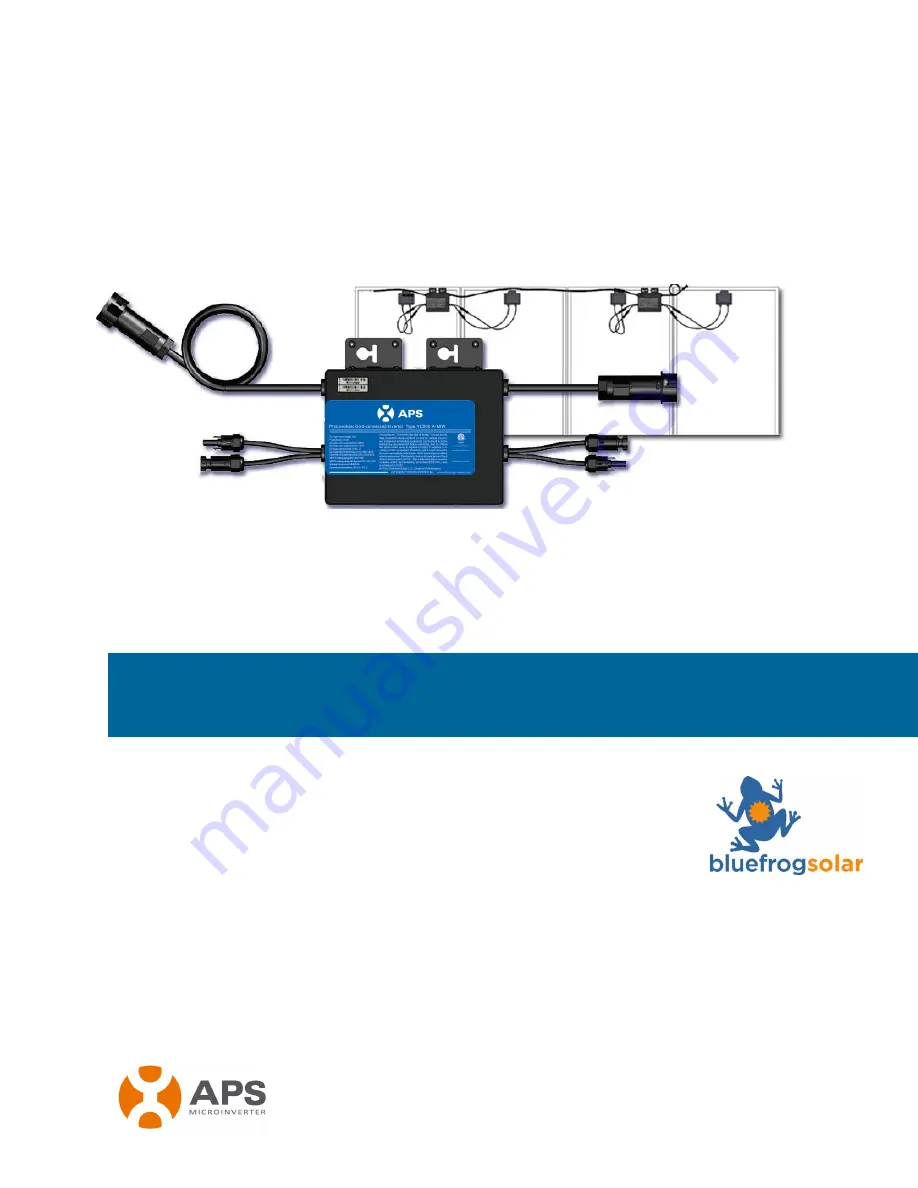
APS YC500A-MIW
Photovoltaic Grid-connected Inverter
Version 4.1 7/2014
APS America
1015 Hostmark St. Ste 104; Poulsbo, WA 98370
TEL:
206-855-5100
EMAIL
: [email protected]
WEB:
www.APSamerica.com
Page 1: ...tion User Manual APS YC500A MIW Photovoltaic Grid connected Inverter Version 4 1 7 2014 APS America 1015 Hostmark St Ste 104 Poulsbo WA 98370 TEL 206 855 5100 EMAIL info apsamerica com WEB www APSamer...
Page 2: ...ecting the APS Microinverter to the PV Module 9 Step 4 Ground the System 10 Step 5 Connecting APS Microinverters to the AC Cables 11 Step 6 Completing the APS Installation Map 12 APS Microinverter sys...
Page 3: ...imized Microinverter operation Follow these instructions closely SAFETY INSTRUCTIONS Do NOT disconnect the PV module from the APS Microinverter without first disconnecting the AC power Only qualified...
Page 4: ...tructions were not followed when installing and using the equipment But there is no guarantee that interference will not occur in a particular installation If this equipment causes harmful interferenc...
Page 5: ...Introduction The APS Microinverter is used in utility interactive grid tied applications comprised of three key elements APS Microinverter APS Energy Communication Unit ECU APS Energy Monitor and Ana...
Page 6: ...failure exists across the PV system APS Microinverters are designed to operate at full power at ambient outdoor temperatures of up to 149 F 65 C The inverter housing is designed for outdoor installati...
Page 7: ...Technical Data page p 18 of this manual The APS YC500 has two independent DC inputs each with independent MPPT control and data monitoring The following figure shows the APS YC500 Microinverter schema...
Page 8: ...please read all instructions and warnings in the technical documents and on the APS Microinverter system itself as well as on the PV array WARNING Be aware that installation of this equipment includes...
Page 9: ...Installing the AC Branch Circuit Junction Box A Install an appropriate junction box at a suitable location on the PV racking system typically at the end of a branch of modules B Connect the open wire...
Page 10: ...rters to the Racking or the PV Module Frame A Mark the location of the Microinverter on the rack keeping in mind the PV module junction box or any other obstructions B Mount one Microinverter at each...
Page 11: ...p 3 Connecting APS Microinverters to the PV Module Connect the DC cables from the PV Modules to the Micro Inverter per the diagram below Note When plugging in the DC cables the Microinverter should im...
Page 12: ...washers WEEB to ground the Microinverter chassis to the PV module racking as described in Step 2C skip this step Each APS Microinverter comes with a ground clamp that can accommodate a single 6 awg st...
Page 13: ...circuit B Install a protective end cap on the open AC connector of the last Microinverter in the AC branch circuit C Plug the AC female connector of the last Microinverter into the male connector of...
Page 14: ...d is designed to accomodate labels in vertical or horizontal orientation to meet all the field PV connections 1 Each APS Microinverter has removable serial number labels Peel a label off and affix it...
Page 15: ...they are producing power normally but have not yet connected to the ECU After the ECU has been plugged in and acknowledges the Microinverters they will start to blink green every 10 seconds 4 Plug in...
Page 16: ...ss the GFDI error has been cleared the LED will remain red and the ECU will keep reporting the fault After the ground fault error is fixed follow the instructions in the ECU Installation and Operation...
Page 17: ...eans it is definitely a Microinverter problem 2 Diagnosing from the ECU a No Data Display This is probably a communication issue not a Microinverter problem b Problems with erratic display Data is dis...
Page 18: ...y grid as described in the previous step 4 Make sure that all AC breakers are functioning properly and are closed 5 Check the DC connections between the Microinverter and the PV module 6 Verify the PV...
Page 19: ...3 Disconnect the PV module DC wire connectors from the micro inverter 4 Remove the Microinverter from the PV array racking B Install a replacement Microinverter to the rack Remember to observe the fl...
Page 20: ...er Refer to the APS website http www altenergy power com for a list of approved PV modules WARNING You must match the DC operating voltage range of the PV module with the allowable input voltage range...
Page 21: ...y 99 5 MECHANICAL DATA Storage Temperature Range 40 F to 185 F 40 C to 85 C Operating Temperature Range Ambient 40 F to 149 F 40 C to 65 C Operating Temperature Range Internal 40 F to 185 F 40 C to 85...
Page 22: ...ncy temperature Curves YC500 NA Efficency Curves ALTENERGY POWER SYSTEM INC 8 Efficiency Curves YC500 NA Efficiency temperature Curves YC500 NA Efficiency Curves ALTENERGY POWER SYSTEM INC 8 Efficienc...
Page 23: ...APS YC500A MIW Installation User Manual 21 Figure 11 Sample Wiring Diagrams Sample Wiring Diagram 120V 240V Three Phase...
Page 24: ...APS YC500A MIW Installation User Manual 22 NOTE The ECU should function properly when connected to L1 L2 or L3 Figure 12 Sample Wiring Diagram 120V 208V Three Phase...
Page 25: ...tion User Manual 23 NOTE The ECU should function properly when connected to L1 L2 or L3 Figure 13 Sample Wiring Diagram 277V 480V Three Phase ALTENERGY POWER SYSTEM INC 24 10 3 Sample Wiring Diagram 2...