4
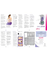
THE THERMOSTAT BUTTONS AND SWITCHES
Before you begin using your thermostat, you should be familiar with
its features and with the display and the location and operation of the
thermostat buttons (see
Figure 8
). Your thermostat consists of two
parts: the
thermostat cover
and the
base
. To remove the cover, gently
pull it straight out from the base. To replace the cover, line up the cover
with the base and press gently until the cover snaps onto the base.
THE DISPLAY
5
Flame icon
( ) is displayed when the SYSTEM switch is in the
HEAT position.
Snowfl ake icon
(
) is displayed (non-fl ashing)
when the SYSTEM switch is in the COOL position.
Snowfl ake
icon
(
) will be displayed (fl ashing) when the compressor is in
lockout mode.
6
Displays current temperature.
7
Displays currently set temperature (this is blank when SYSTEM
switch is in the OFF position).
CHECK THERMOSTAT OPERATION
COOLING SYSTEM
HEATING SYSTEM
1. Move SYSTEM switch to
HEAT
position. If the heating system has
a standing pilot, be sure to light it.
2. Press
to adjust thermostat setting above room temperature.
The heating system should begin to operate.
3. Press
to adjust temperature setting below room
temperature. The heating system should stop operating.
1
4
6
5
3
2
7
OPERATING FEATURES
Now that you are familiar with the thermostat buttons and display,
read the following information to learn about the many features of
the thermostat.
•
SIMULTANEOUS HEATING/COOLING SETPOINT STORAGE
–
You can enter both your heating and cooling setpoints at the same
time. There is no need to re-enter the setpoint at the beginning of
each season.
•
TEMPERATURE SETTING
– Press
or
until the display
shows the temperature you want. The thermostat will keep the
room temperature at the selected temperature.
•
°F/°C CONVERTIBILITY
– The factory default setting is
Fahrenheit. If you need Celsius temperature to be displayed, go
to menu mode and change the 6th option to C (see Confi guration
Menu, page 5).
•
TEMPERATURE DISPLAY ADJUSTMENT
– Your new
thermostat has been accurately set in our factory. However, if you
wish, you may adjust your new thermostat temperature display
to match your old thermostat. This can be accomplished (within a
±4° range) by going into the menu mode (see Confi guration Menu,
page 5).
NOTE: To prevent static discharge problems, touch side
of thermostat to release static build-up before touching
any keys.
If at any time during testing your system does not operate properly,
contact a qualifi ed service person.
FAN OPERATION
If your system
does not
have a
G
terminal connection, skip to
Heating System
.
1. Turn on power to the system.
2. Move fan switch to
ON
position. The blower should begin to operate.
3. Move fan switch to
AUTO
position. The blower should stop
immediately.
To prevent compressor and/or property damage, if the
outdoor temperature is below 50°F, DO NOT operate the
cooling system.
CAUTION
1
(Up arrow) Raises
temperature setting.
2
(Down arrow)
Lowers temperature
setting.
3
FAN switch
(
ON, AUTO
).
4
SYSTEM switch
(
COOL, OFF, HEAT
).
Do not set to OFF mode during periods when freezing
temperatures could occur.
CAUTION
This thermostat has a time delay between cooling cycles to allow
the head pressure in the compressor to stabilize. If the temperature
is adjusted to call for cool within 5 minutes of the last cycle the
Snowfl ake icon
(
) will blink indicating the thermostat is locked
out. After 3 to 5 minutes, the compressor will start and the
Snowfl ake
icon
(
) will stop fl ashing. This helps prevent the compressor from
cycling too quickly and is normal operation for the thermostat.
1. Move SYSTEM switch to
COOL
position.
2. Press
to adjust thermostat setting below room temperature.
The blower should come on immediately on high speed, followed by
cold air circulation.
3. Press
to adjust temperature setting above room temperature.
The cooling system should stop operating.
FIGURE 8 – Thermostat buttons,
display and switches