2–6
PacketMax 5000 Installation and Operation Manual, 10007678 Rev J
Chapter 2. Base Station Components
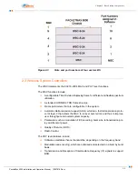
Each WSC has a wireless interface port that connects via a coax cable to the outdoor-
mounted BSR. The WSC uses a 70 MHz IF signal to transport traffic control signals
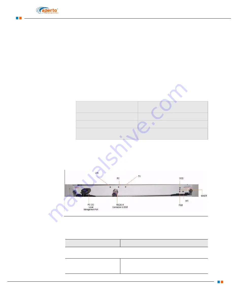
and power to the base station radio. The WSC card interfaces are labelled in
WSC cards are hot swappable, and can be replaced or added without having to
shutdown the PM 5000 Base Station or disrupt traffic passing through other WSC
cards.
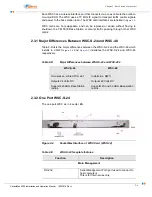
2.3.1 Major Differences Between WSC-S-24 and WSC-48
Table 2-D lists the major differences between the WSC-S-24 and the WSC-48 which
installs in a QWC.
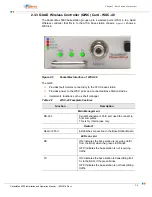
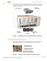
and
illustrates the WSC-S-24 and WSC-48
respectively.
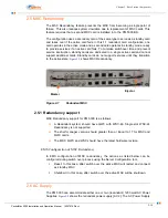
2.3.2 One Port WSC-S-24
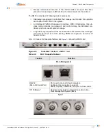
The one port WSC as in 4 sector BS.
Figure 2-4
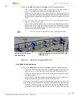
PacketMax Interface of WSC Card (WSC-24)
Table 2-D
Major Differences between WSC-S-24 and WSC-48’s
WSC-S-24
WSC-48
Occupies an entire ATCA slot
Installs in a QWC
Outputs 24 Volts DC
Outputs 48 Volts DC
Supports 20 dBm Base Station
radios
Supports 20 and 30 dBm Base station
radios
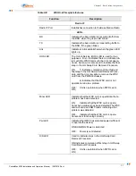
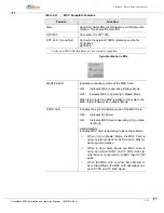
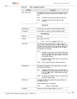
Table 2-E
WSC-S-24 faceplate features
Function
Description
Main Management
RS-232
Serial Management Port/ port used to connect to
host computers.
This is for Internal use only.
Summary of Contents for PacketMAX 5000
Page 10: ...Preface Preface vi PacketMax 5000 Installation and Operation Manual 10007678 Rev J ...
Page 14: ...Table Of Content TOC 4 PacketMax 5000 Installation and Operation Manual 10007678 Rev J ...
Page 146: ...E 4 PacketMax 5000 Installation and Operation Manual 10007678 Rev J Chapter E Certifications ...
Page 150: ...F 4 PacketMax 5000 Installation and Operation Manual 10007678 Rev J Chapter F Troubleshooting ...

