background image


60


1. 

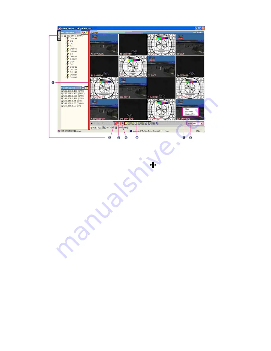
Adjust the screen size: 

Move the mouse to the vertical bar on the right side of 

the 

"Work Devices" / "Available Devices" 

box on the left margin of the 

screen. This bar runs from the top to the bottom of the screen, and when you 
move the mouse to this bar, it shows like this:          . You can move this bar to 
the left to narrow the 

"Working Devices" / "Available Devices" 

box and to the 

right to widen it.


2. Hide 

Device 

Panel: 

Click this button to hide the 

"Available Devices / 

Working Devices" 

box from view behind the video display screen. 

3. 

Full Screen: 

Click this button to show the full screen for surveillance. All the 

setting buttons will be hidden in this mode. If you want to return to the previous 
mode, use the mouse to click the right key, and choose

 "Close"

.


4. 

Re-arrange the divisions: 

Click this button to see the following channels.


5. 

Screen divisions: 

Choose any of the buttons you want.


6. 

LAN or Internet mode: 

Click this button to enter the 

"LAN" 

and 

"Internet" 

modes alternately.


7. 

Pop-menu: 

You can use the mouse to move to each channel. Click the right 

key of the mouse to show a window. You can select 

"Close", "Full Screen", 

or


"Capture / Print"

.


※ 

Close:

 Stops the channel's display.


※ 

Full Screen: 

Enlarges the display to 

"Full Screen"

.


※ 

Capture / Print:


"Capture":  

See the 

"Image Preview" 

page for the 

"Preview Setting" 

which has two choices :


"Mark Date and Time" 

and 

"Dimension"

.


Mark


the item “

Mark Date and Time

” to 

set the date and time stamp on a chosen picture. Choose an appropriate dimension 
before saving the image.


To save the image, click 

"Save" 

at the bottom to enter the


"Save Page" 

window. Give the file name. If you want to exit, click

 "Cancel"

.


Summary of Contents for DVR-3016, DVR-3016D

Page 1: ...Before trying to connect or operate this product please read this manual complete INSTALLATION OPERATING MANUAL Digital Video Recorder DVR 3016 DVR 3016D ...

Page 2: ......

Page 3: ...shock hazard CAUTION Danger of explosion if the Lithium battery RTC Battery is incorrectly replaced Danger of explosion if battery is incorrectly replaced Replace only with the same or equivalent type recommended by the manufacturer Dispose of used batteries according to the manufacturer s instructions Risk of explosion if replaced by an incorrect type Dispose of used batteries according to the in...

Page 4: ...t Forward Reverse 20 4 2 2 Slow Forward Reverse 20 4 2 3 Playback Picture by picture 21 4 2 4 Play Back Recorded Video from a HDD of the mobile rack FOR REMOVABLE HDD MODEL ONLY 21 4 3 Search Operations 22 4 3 1 Full List Search 22 4 3 2 Alarm list Search 22 4 3 3 SEARCH FILTER 23 4 3 4 THUMBNAIL Search 24 4 3 5 SD CARD Menu 24 4 3 6 CD BACKUP Menu 25 4 4 Backup Operations 26 4 4 1 CD ReWritable u...

Page 5: ... PASSWORD SETTING 48 5 9 EXIT MENU 49 6 NETGUARD SYSTEM Introduction 50 6 1 TCP IP Communication Setup 51 6 2 Connection Testing 54 6 3 Software installation 55 6 4 Short introduction 58 6 4 1 Program introduction 58 6 5 Operation 59 6 5 1 Remote Control 59 6 5 2 Remote play and PTZ control 62 6 5 3 Backup and video edit 63 6 5 4 Web Page Viewer 65 6 5 5 Viewer setting 66 6 6 The Image Viewer 68 7...

Page 6: ...h simultaneous Live Play Record and remote Network operations Pre alarm image recording 10 seconds in advance Every camera can be assigned to any channel location under a multi screen display mode in both live viewing and playback mode 16 way 13 way 10 way 9 way 8 way 6 way 4 way 3 way 2 way Refresh rate up to 60 field sec for 720X240 NTSC or 50 field sec for 720X288 PAL Compression Motion JPEG Qu...

Page 7: ...ion Individual alarm sensor video loss alarm motion detection alarm for each channel Power interruption recovery Operation status record log Multi lock out functions front key lock RS 232 lock play back lock and recording lock Three audio quality levels 8 22 44 kHz sampling μ law Audio recording modes stereo left right off Built in SD memory card slot to save JPEG AVI image s for individual channe...

Page 8: ...een interrupted or it is impossible to eject a disc please use a pin to press the emergency eject button so that the caddy will eject the disc FOR REMOVABLE HDD MODEL 1 Hard disk drive compartment The compartment allows you to install a hard disk drive mostly for backup purposes Make sure the drive is well secured with the mounting screws in the mobile rack before you put the rack into the compart...

Page 9: ...ou can open the SD CARD Menu to save the image s 10 REC button Push to start recording video into a hard disk while in the live display mode Press again for at least 3 seconds to stop the recording NOTE The monitor will display a message STOP RECORD if you power off the device in case of recording 11 Left button Press to move the focus to desired items in the menu setup mode In the live and play m...

Page 10: ...n both the particular image and the entire image record are halted 21 search button Press to enter the search mode to access recorded video 22 zoom button Press to double the size of an image Use the up V down left and right buttons to shift your zoom focus Press the zoom button again to return to the original image size 23 channel button All channel buttons from 1 to 16 are sited here Press each ...

Page 11: ...ol buttons in the front panel to the main monitor This connector transmits the video display in full screen format multi screen format and sequential format 35 Ground Screw s The ground screw is for the chassis terminal 36 37 Left Right AUDIO IN Connector These two connectors are used to connect the audio output from a camera or other devices to the 16CH DVR 38 39 Left Right AUDIO OUT These two co...

Page 12: ... ALARM12 IN INPUT 11 ALARM13 IN INPUT 24 ALARM14 IN INPUT 12 ALARM15 IN INPUT 25 ALARM16 IN INPUT 13 NO CONNECTION NOTE THIS FIGURE IS SEEN FROM THE REAR VIEW GROUND Ground Contact DISK FULL OUTPUT This is a disk full output trigger Connect this to external devices such as buzzers or lights 5V 0V Active ALARM OUT OUTPUT This is an alarm output trigger Connect this to external devices such as buzze...

Page 13: ...he instructions and the diagram below to set up the system 3 1 Basic Connection CONNECTING WITH 1 to 16 CAMERAS ATTACHING AN EXTERNAL DEVICE TO DVR Connect an alarm out alarm input and a peripheral device as shown in the diagram below ...

Page 14: ...ne hard disk drive in the mobile compartment please set the HDD3 USAGE option to REC please refer to section 4 4 before proceed recording function Table 3 2 B Compatible hard disk drives Manufacturer Model Capacity Rotation ST380020A P 80GB 5400 RPM ST340810A P 40GB 5400 RPM ST320014A 20GB 5400 RPM ST340015A 40GB 5400 RPM ST380012ACE 80GB 5400 RPM Seagate ST3120025ACE 120GB 5400 RPM 4A160J0 1A 160...

Page 15: ...1 hours and 10 minutes remaining time available REC MODE STOP MANUAL STATUS Indicates the device status PLAY The device is in the playback mode LIVE The device is in the live display mode MANU The device is in the search mode SCHEDULE NORMAL and 1 8 Press the Display button again the unit will display the information as shown in Figure 3 3 C below Figure 3 3 C Description of Figure 3 3 C DHCP Enab...

Page 16: ...p holding down the buttons until the 16CH DVR sounds a note and displays the message LOAD PROGRAM Now the 16CH DVR is updating the system software taking approximately 150 seconds to complete 7 Restart the unit by turning off the DVR when the device displays the message PLEASE POWER OFF RESTART Then turn on the DVR again The process is complete If you have already followed procedures 1 6 and the u...

Page 17: ...s This way the DVR will start and stop recording according to the programmed schedule Please take the following steps to program the scheduled recording 1 Press the menu button to enter the MAIN MENU 2 Select the ADVANCED SETTING and press the Enter button to enter the ADVANCED SETTING page 3 Select SCHEDULE and press the Enter button to enter the SCHEDULE SETTING page 4 Choose a schedule and enab...

Page 18: ...ng is complete and come out from the menu to start recording NOTE If you activate the recording function before the scheduled recording the unit will operate recording as shown in the diagram below and keep those Images in different files 03 00 06 00 08 00 12 00 14 00 START END START END Start Manual Recording Timer Manual Timer Manual ...

Page 19: ...CHEDULE6 DISABLE ENTER 7 SCHEDULE7 DISABLE ENTER 8 SCHEDULE8 DISABLE ENTER RETURN menu exit enter select shuttle value jog ch1 8 item SCHEDULE SETTING 1 DATE WEEKLY 2 START TIME 12 00 3 END TIME 12 00 4 START RECORD YES 5 ALARM SETTING DISABLE ENTER 6 RECORD SETTING DISABLE ENTER 7 MOTION SETTING DISABLE ENTER RETURN menu exit enter select shuttle value jog ch1 7 item MAIN MENU 1 QUICK SETTING ENT...

Page 20: ...namely START RECORD Change it to ON under ACTIVE to start alarm recording MAIN MENU 1 QUICK SETTING ENTER 2 DISPLAY OPTION ENTER 3 SEQUENCE SETTING ENTER 4 PICTURE ADJUST ENTER 5 OPERATION LOG ENTER 6 ADVANCED SETTING ENTER 7 DEFAULT SETTING ENTER 8 PASSWORD SETTING ENTER 9 EXIT MENU ENTER enter select jog ch1 9 item ADVANCED SETTING 1 ALARM SETTING ENTER 2 RECORD SETTING ENTER 3 MOTION SETTING EN...

Page 21: ...ng operations when an alarm takes place is shown in the diagrams below 1 2 3 4 Manual or Externally Triggered Recording Alarm Takes Place Actual Recording Speed Normal Alarm Normal Timer Recording Actual Recording Speed Alarm Takes Place Timer Recording Actual Recording Speed Alarm Takes Place Timer Recording Actual Recording Speed Alarm Takes Place Normal Alarm Normal Normal Alarm Alarm Normal ...

Page 22: ...the forward rate as 2x 4x 8x 16x 30x and 100x Reverse Turn the Shuttle dial to the left to view the recorded video in the reverse direction at a speed faster than the recorded speed Each subsequent turn of the shuttle to the left increases the reverse rate as 2x 4x 8x 16x 30x and 100x Normal Release the Shuttle dial to return to the normal speed of playback 4 2 2 Slow Forward Reverse There are 6 s...

Page 23: ... picture at a time in the forward direction Turn the JOG dial counterclockwise to display one frame of a picture at a time in the backward direction 3 Press the PLAY button to return to the normal speed of playback 4 2 4 Play Back Recorded Video from a HDD of the mobile rack FOR REMOVABLE HDD MODEL ONLY To play back a recorded video from a HD3 take the following steps 1 Press the Search button to ...

Page 24: ...g steps to proceed with the alarm list search function 1 Press the Search button to enter the search mode 2 Select the ALARM LIST and press the Enter button to access the complete list of alarm event recorded video 3 Highlight the specific recorded video of your requirement and press the Enter button to display the selected video Key Operation Press the and v buttons to select a video press the an...

Page 25: ...age and repeat steps 3 and 6 again for another search CD IS FOR THE CD ROM MODEL AND BACKUP IS FOR THE REMOVABLE HDD MODEL ONLY IN THE ITEM 6 SEARCH 1 FULL LIST ENTER 2 ALARM LIST ENTER 3 SEARCH FILTER ENTER 4 THUMBNAIL ENTER 5 SD CARD ENTER 6 CD BACKUP ENTER 7 EXIT ENTER enter select jog ch1 7 item HD NO DATE TIME ALARM HD1 0001 05 11 2004 12 15 03PM CH3 VLOS 0002 14 30 43PM CH4 VLOS 0003 05 16 2...

Page 26: ...n CD IS FOR THE CD ROM MODEL AND BACKUP IS FOR THE REMOVABLE HDD MODEL ONLY IN THE ITEM 6 4 3 5 SD CARD Menu Take the following steps to proceed with the SD card search function 1 Insert an SD Card into the SD card slot of the front unit 2 Press the Search button to enter the search mode 3 Select the SD CARD and press the Enter button to access the complete list of JPEG files 4 Highlight the speci...

Page 27: ...e the picture below for this status and please insert a CD or press the search button to exit the CD menu SEARCH 1 FULL LIST ENTER 2 ALARM LIST ENTER 3 SEARCH FILTER ENTER 4 THUMBNAIL ENTER 5 SD CARD ENTER 6 CD BACKUP ENTER 7 EXIT ENTER enter select jog ch1 7 item SD CARD MENU 1 05 13 2004 12 49 12PM JPG0001 JPG 2 05 13 2004 12 50 33PM JPG0002 JPG 3 05 13 2004 12 51 45PM JPG0003 JPG 4 05 13 2004 1...

Page 28: ... If you wish to add more images to the buffer press any key to return to the CD JPEG MENU vi Turn the jog dial to find the next image you want Now repeat the last step again to add this image to the buffer You can continue in this way indefinitely vii If you now wish to edit your buffer select item 2 EDIT JPEG in the CD JPEG MENU Now in the EDIT JPEG page turn the jog dial to review your selected ...

Page 29: ...n 10seconds and 10minutes Item 4 Enter this item to start burning your video in the CD disc vi Press the eject button to open the CD tray take out the CD disc and enter it in a PC to view your video 4 4 2 Mobile Rack HD Backup Operations FOR REMOVABLE HDD MODEL ONLY There are three ways available to duplicate the recorded video from HDD1 and HDD2 Fixed HDs in HDD3 the Mobile Rack HD Please take th...

Page 30: ...ING ENTER 2 RECORD SETTING ENTER 3 MOTION SETTING ENTER 4 CAMERA COVERT ENTER 5 OPERATION LOCK ENTER 6 COMMUNICATION ENTER 7 DISK SETUP ENTER 8 SCHEDULE ENTER RETURN menu exit enter select jog ch1 8 item DISK SETUP 1 DISK FULL REWRITE 2 HDD1 REFORMAT ENTER 3 HDD2 REFORMAT ENTER 4 HDD3 REMOVEABLE REFORMAT ENTER 5 SD CARD REFORMAT ENTER 6 HDD3 REMOVEABLE USAGE BACKUP HD 7 RETURN HD1 MODEL ST320014A ...

Page 31: ...d file names will be assigned in sequence as shown below SAVE JPG0001 JPG TO SD CARD SAVE JPG0002 JPG TO SD CARD SAVE JPG000N JPG TO SD CARD 2 Archive video of AVI Clips into an SD Card Please take the following steps to archive a critical video in an SD card 1 Insert an SD Card into the SD card slot of the front unit 2 Start playing back the recorded video and select a desired channel 3 Press the...

Page 32: ...nter the saving mode Set SAVE SD CARD SETTING to YES Then the system setting info will auto save into the SD card Transfer the system setting info of a DVR to another Insert the SD card which has stored the system setting info into the DVR Press the menu button to enter the MAIN MENU page Highlight DEFAULT SETTING and press the Enter button to enter the DEFAULT SETTING page Select the LOAD SD CARD...

Page 33: ...ctivate the key lock function turn the FRONT KEY LOCK to OFF MAIN MENU 1 QUICK SETTING ENTER 2 DISPLAY OPTION ENTER 3 SEQUENCE SETTING ENTER 4 PICTURE ADJUST ENTER 5 OPERATION LOG ENTER 6 ADVANCED SETTING ENTER 7 DEFAULT SETTING ENTER 8 PASSWORD SETTING ENTER 9 EXIT MENU ENTER enter select jog ch1 9 item ADVANCED SETTING 1 ALARM SETTING ENTER 2 RECORD SETTING ENTER 3 MOTION SETTING ENTER 4 CAMERA ...

Page 34: ...nd so on to the other channels consecutively until you arrive at your chosen channel 4 Click any specific channel button to show that channel s recorded images in the play mode in the particular space you ve arrived at Simultaneous Live and Play on Screen functions 1 Press the search button to enter the SEARCH page to select a recorded video Play the record 2 Press the PAUSE button to halt the ima...

Page 35: ...menu button Press to enter the MAIN MENU page You can also use this button to return directly to the MAIN MENU page from any other page After returning to the MAIN MENU page you can push the menu button again and then enter to exit the menu system page and v buttons Press to select a desired item and buttons Press to move within a desired option or value Enter button Press to enter a selected item...

Page 36: ...y range from BEST HIGH and STANDARD to BASIC 6 DISK FULL This option determines the way to utilize storage media in case of a full disk REWRITE When the hard disk is full the device continues recording by displacing the old data STOP When the hard disk is full the device will stop recording NOTE Please press the STOP or DISPLAY buttons to erase the beeping sound 7 RETURN Choose this item and press...

Page 37: ...ATION LOG ENTER 6 ADVANCED SETTING ENTER 7 DEFAULT SETTING ENTER 8 PASSWORD SETTING ENTER 9 EXIT MENU ENTER enter select jog ch1 9 item DISPLAY OPTION 1 TIME MODE 12HR 2 TIME SETTING 05 40 55PM 3 DATE MODE MM DD YYYY 4 DATE SETTING 05 02 2004 5 TIME ZONE GMT 00 00 6 TITLE SETTING ENTER 7 MAIN MONITOR DISPLAY ENTER 8 CALL MONITOR DISPLAY ENTER 9 DAYLIGHT SAVING SETTING ENTER RETURN menu exit enter ...

Page 38: ...nable to ON to activate the call monitor and disable to OFF 2 DATE DISPLAY The option once more is ON to enable and OFF to disable 3 TIME DATE LOCATION The time and date labels can be placed at or changed to any of six positions top left top mid and top right and bottom left bottom mid and bottom right 4 TITLE DISPLAY Once again turn ON to activate and OFF to deactivate 5 RETURN Go back to the pre...

Page 39: ...saving time begins at 3 00 a m on the last Sunday of March Time reverts to standard time at 4 00 a m on the last Sunday of October 5 RUSSIA Daylight saving time begins at 2 00 a m on the last Sunday of March Time reverts to standard time at 3 00 a m on the last Sunday of October 6 NORTH AMERICA Daylight saving time begins at 1 00 a m on the first Sunday of April Time reverts to standard time at 2 ...

Page 40: ... sequential 8 9 CHANNEL DISPLAY 9 windows one sequential 9 10 CHANNEL DISPLAY 10 windows one sequential 10 13 CHANNEL DISPLAY 13 windows one sequential 11 FULL SCREEN DISPLAY Set the call monitor s sequence mode with the preferred dwell time for each channel 12 RETURN Choose this item and press the Enter button to go back to the previous page MAIN MENU 1 QUICK SETTING ENTER 2 DISPLAY OPTION ENTER ...

Page 41: ... SEQUENCE SETTING ENTER 4 PICTURE ADJUST ENTER 5 OPERATION LOG ENTER 6 ADVANCED SETTING ENTER 7 DEFAULT SETTING ENTER 8 PASSWORD SETTING ENTER 9 EXIT MENU ENTER enter select jog ch1 9 item PICTURE ADJUST 1 H POSITION 0 2 V POSITION 0 3 LIVE PICTURE ENTER 4 COLOR BAR PATTERN ENTER RETURN menu exit enter select shuttle value jog ch1 4 item MAIN MENU 1 QUICK SETTING ENTER 2 DISPLAY OPTION ENTER 3 SEQ...

Page 42: ...ion MAIN MENU 1 QUICK SETTING ENTER 2 DISPLAY OPTION ENTER 3 SEQUENCE SETTING ENTER 4 PICTURE ADJUST ENTER 5 OPERATION LOG ENTER 6 ADVANCED SETTING ENTER 7 DEFAULT SETTING ENTER 8 PASSWORD SETTING ENTER 9 EXIT MENU ENTER enter select jog ch1 9 item ADVANCED SETTING 1 ALARM SETTING ENTER 2 RECORD SETTING ENTER 3 MOTION SETTING ENTER 4 CAMERA COVERT ENTER 5 OPERATION LOCK ENTER 6 COMMUNICATION ENTER...

Page 43: ...nd ACTIVE 9 ALARM OUT LINK Enter and activate YES or deactivate NO the three alarm output modes of SENSOR V LOSS and ACTIVE for the following ALARM OUT 1 2 and 3 BUZZER MAIN and CALL DISPLAYs START RECORDING and CALL FULL SCREEN 10 RETURN Go back to the previous page 5 6 2 RECORD SETTING This page enables you to set the recording rate and recording quality and enables you to continue recording if ...

Page 44: ...itivity bar and change the focus left to right 2 TARGET ZONE With AUTO or MANUAL setting 3 TRACK DETECT Ranging from UP and DOWN to LEFT and RIGHT 4 DURATION The rate of recorded image movements ranging from 0 0 to 5 0 seconds 5 SIZE Determine which size targets you want detected ranging from 1H1W to 9H9W 6 RETURN Go back to the previous page ADVANCED SETTING 1 ALARM SETTING ENTER 2 RECORD SETTING...

Page 45: ...NCED SETTING 1 ALARM SETTING ENTER 2 RECORD SETTING ENTER 3 MOTION SETTING ENTER 4 CAMERA COVERT ENTER 5 OPERATION LOCK ENTER 6 COMMUNICATION ENTER 7 DISK SETUP ENTER 8 SCHEDULE ENTER RETURN menu exit enter select jog ch1 8 item CAMERA COVERT CH1 ON menu exit CH2 OFF shuttle value CH3 OFF jog ch1 16 item CH4 OFF CH5 OFF CH6 OFF CH7 OFF CH8 OFF CH9 OFF CH10 OFF CH11 OFF CH12 OFF CH13 OFF CH14 OFF C...

Page 46: ...server the 16CH DVR can get an IP automatically by setting the DHCP item to ON 4 RETURN Go back to the previous page ADVANCED SETTING 1 ALARM SETTING ENTER 2 RECORD SETTING ENTER 3 MOTION SETTING ENTER 4 CAMERA COVERT ENTER 5 OPERATION LOCK ENTER 6 COMMUNICATION ENTER 7 DISK SETUP ENTER 8 SCHEDULE ENTER RETURN menu exit enter select jog ch1 8 item COMMUNICATION 1 RS 232 SETTING ENTER 2 RS 485 SETT...

Page 47: ...lear out all the data in the SD card You will be required to re check your selection before proceeding with clearing out the data and set and enter the SD CARD FORMAT MENU to activate YES or alternatively deactivate NO 7 CD REFORMAT FOR CD ROM MODEL ONLY This item helps you erase your CD disc if it s rewritable 8 HDD3 REMOVABLE USAGE FOR REMOVABLE HDD MODEL ONLY There are two options here for the ...

Page 48: ...CHEDULE1 DISABLE ENTER 2 SCHEDULE2 DISABLE ENTER 3 SCHEDULE3 DISABLE ENTER 4 SCHEDULE4 DISABLE ENTER 5 SCHEDULE5 DISABLE ENTER 6 SCHEDULE6 DISABLE ENTER 7 SCHEDULE7 DISABLE ENTER 8 SCHEDULE8 DISABLE ENTER RETURN menu exit enter select shuttle value jog ch1 8 item SCHEDULE SETTING 1 DATE WEEKLY 2 START TIME 12 00 3 END TIME 12 00 4 START RECORD YES 5 ALARM SETTING DISABLE ENTER 6 RECORD SETTING DIS...

Page 49: ...n find the model number the software version and the date of the latest firmware improvement 7 RETURN Go back to the previous page ADVANCED SETTING 1 ALARM SETTING ENTER 2 RECORD SETTING ENTER 3 MOTION SETTING ENTER 4 CAMERA COVERT ENTER 5 OPERATION LOCK ENTER 6 COMMUNICATION ENTER 7 DISK SETUP ENTER 8 SCHEDULE ENTER RETURN menu exit enter select jog ch1 8 item MAIN MENU 1 QUICK SETTING ENTER 2 DI...

Page 50: ...antly the screen shows the following entry ENTER NEW DEFAULT PASSWORD Type in your selected new default password in a 4 digit number RE ENTER DEFAULT PASSWORD Re type your new default password in order to check it 4 REFORMAT PASSWORD This option allows you to set a password to block any unauthorized entry in formatting Hard disk CD or SD card ENTER NEW REFORMAT PASSWORD Type in the 4 digit number ...

Page 51: ...it 3 RETURN Go back to the previous page MAIN MENU 1 QUICK SETTING ENTER 2 DISPLAY OPTION ENTER 3 SEQUENCE SETTING ENTER 4 PICTURE ADJUST ENTER 5 OPERATION LOG ENTER 6 ADVANCED SETTING ENTER 7 DEFAULT SETTING ENTER 8 PASSWORD SETTING ENTER 9 EXIT MENU ENTER enter select jog ch1 9 item EXIT MENU 1 EXIT MENU WITH SAVING ENTER 2 EXIT WITHOUT SAVING ENTER RETURN menu exit enter select jog ch1 2 item ...

Page 52: ...tures of this NETGUARD This software supports the multiple functions of the network It can search any number of DVRs as necessary It can support eight display modes and help you control your favorite screen sizes It has an extremely powerful search mode to help you search recorded data for the event time you want It supports your local PC simultaneously with the DVR backup data The programs can be...

Page 53: ...ram into your computer 1 Click the Start Menu from your computer and point to the Control panel 2 Click the Network Connections icon twice to enter the Network setting windows Point to the Local Area Connection and click the right bottom of the mouse Click the Properties to enter the Local Area Connection ...

Page 54: ...network components list If the TCP IP is included please process step 5 If it is not included please follow step 4 to install the TCP IP 4 TCP IP installation During the installation you will be requested to insert the windows XP CD ROM After installation the PC will be restarted ...

Page 55: ...provider If you are using a DHCP server please select Obtain an IP address automatically Any assigned IP address for the connected DVRs must be in the same class type as the server If there is no DHCP server please select specify an IP address and type in the IP address of your PC This IP address must be different from the DVR IP but in the same class type NOTE The IP address of a DVR in a network...

Page 56: ...2 168 1 1 then Enter See the sample screen below This IP is the DVR IP address that is assigned for the connected DVR 3 If you receive a response as in the sample screen below the connection hasn t been successfully established Please re check all the hardware and software installation by repeating steps 1 to 5 If you still can t establish the connection after rechecking please contact your dealer...

Page 57: ...ill execute the installation of the Net Framework automatically after you click the Setup exe file Note If you choose Yes in the above window the installation will be completed automatically You may need to wait 3 5 minutes during the installation Step 3 After you have completed installing the Net 1 22 Framework Viewer you ll automatically enter the NETGUARD SYSTEM installation screen Please see t...

Page 58: ...ow the message C Program Files NETGUARD Or you can select the path you want Note Click Next to continue the installation Step 5 The window below tells you the process is complete Note Click the Close button to complete the installation process ...

Page 59: ...ge Then click the NETGURD SYSTEM tag to start the program NOTE Please make sure the TCP IP communication software has been properly set and configured in your computer NOTE Auto Uninstall It s not necessary to remove the exit program when you are going to install a new version of NETGUARD Every time you update the NETGUARD the original version will be removed automatically ...

Page 60: ...ogram introduction Available Devices Here the whole DVR list is shown You can connect with your selection Double click any of them to open the screen below Please enter the correct Username and Password to log into this DVR The default Username and Password are admin and 9999 respectively Wording Device After you enter the DVR the section in the upper left margin will show the information in all t...

Page 61: ...ter entering the NETGUARD please click the button to select 16 Channels DVR and then click the Available Devices button The software will automatically search the whole local LAN 16 channel DVR device to see a list Step 2 Double click your selected device to see a window as on the right Enter the Username and Password the default name and password are admin and 9999 Step 3 The default multi screen...

Page 62: ...ouse to click the right key and choose Close 4 Re arrange the divisions Click this button to see the following channels 5 Screen divisions Choose any of the buttons you want 6 LAN or Internet mode Click this button to enter the LAN and Internet modes alternately 7 Pop menu You can use the mouse to move to each channel Click the right key of the mouse to show a window You can select Close Full Scre...

Page 63: ...t the image size Go to the Print Settings area and then to Mark Date and Time if you wish to stamp the date and time of the image on the image itself Select Dimension to scroll the appropriate pixels from the drop down list Click Print to start the printing Click Cancel to exit ...

Page 64: ... search entries to help your search Pause Click to freeze the image Stop Click to stop playing back the recorded video Step Forward Click to view images picture by picture in the forward direction Step Backward Click to view images picture by picture in the reverse direction FWD Click to play a recorded video in the forward direction at speeds which are faster than the recorded speed REV Click to ...

Page 65: ...era angle by angle in the set positions Each of the ten buttons under Clear can be clicked to delete the corresponding Set button above it For example if you wish to de activate Set button 4 please click Clear button 4 to delete its corresponding Set counterpart Each of the ten buttons designated Go to can be clicked to view the particular corresponding angle of the position in which it is set 7 T...

Page 66: ...backup button If you want to stop click the Stop backup button Edit File Path To set the backup file and the file name check the Browser button on the right Click Edit Selected File to start editing Frame Rate Modification To see the total number of frames modify your frame rate File Preview Click the Start button to start your setting component You can also use the Start button to interrupt the c...

Page 67: ...e control panel and remote control the pan tilt zoom function camera live over a local area network or the Internet 2 Enter the General Setting page to set the title the date and time modes and the date and time of the device Click Submit after each setting 3 Click Advance Setting to enter four pages the Image Alarm Record and User pages ...

Page 68: ...window you can set the device s Disk Full Frame Rate Audio Rate and Audio Channel entries In the lower part of the window set each channel s Select Channel and Quality Click Submit after each setting User Click User to enter the User Setting page and set the device s User Name Password New Password and Confirm Click Submit to set NOTE This device also provides remote control and viewing capabiliti...

Page 69: ...conds for both entries as per your requirements The Scan Working Devices entry has a time span of 1 to 5 seconds only The Scan Available Devices time range covers 30 to 1000 seconds 5 Users Management Click the Save User button to add the new user s name and password under Add New User Enter the User Name and Password and click Save User again Your new user and his password will appear on the User...

Page 70: ...o start the Image View program See a sample screen below This is image integrity protection software It not only allows you to view an archived image from the SD card or HDD of a computer but also protects an archived image from reproduction or interpolation If an image isn t in the original format form of our 16CH DVR the Image Viewer will not display the image and instead will send a warning mes...

Page 71: ...me and password is admin and 9999 respectively 3 Enter the user name Login Name 4 Fill in the password Password 5 Click the OK button and enter the home page of the 16CH DVR both the user name and password must be provided correctly Description of functional keys User Name Enter the user name in the blank space Password Fill in the password in the blank space OK button Click to enter the home page...

Page 72: ...allows you to display the connected device in the multi format screens of 1 2x2 3x3 and 4x4 Recorded video list box This box allows you to access all recorded video which are stored in the HDD of the connected devices To review a recorded video simply select an entry from the list and click the button PgUp PgDn Enables you to scroll up and down the list This allows you to search a recorded video s...

Page 73: ...per part of the window enables you to set the Duration Disk Full PreAlarm and Frame Rate of the alarm for the device The bottom part of the window helps you set each channel s settings in the event of an alarm Set Select Channel Record Mode Quality Sensor Type Sensor Sensitivity Sensor Output Video Loss Output and Motion Output for each channel Click Submit to set your changes Record Click Record ...

Page 74: ...ward Reverse 1X 2X 4X 8X 16X 30X 100X Slow Forward Reverse 1 2X 1 4X 1 8X 1 16X 1 30X 1 100 and pause Search Event List Time Alarm List Filter Thumbnail SD Card Event List Time Alarm List Filter Thumbnail SD Card CD Zoom X2 Motion Detection Advanced MD Zone Position Sensitivity OSD Cam Title Time Date Mode Error Message Set up Menu Advanced Quick Network setting Log List 2048 Record Operation Log ...

Page 75: ... 1 stop bit and no parity Four different speeds can be used 1200 baud per second 2400 baud 4800 baud and 9600 baud The default setting is 2400 baud per second When only one device is controlled via RS 232 RS 485 port from a host computer the control command codes should contain an L0 to instruct the device to enter operation mode Other command codes starting with L are not necessary When a compute...

Page 76: ...ized character Key codes will clear the alarm 1 Same as CH1 Selection button 2 Same as CH2 Selection button 3 Same as CH3 Selection button 4 Same as CH4 Selection button 5 Same as CH5 Selection button 6 Same as CH6 Selection button 7 Same as CH7 Selection button 8 Same as CH8 Selection button 9 Same as CH9 Selection button 10 Same as CH10 Selection button 11 Same as CH11 Selection button 12 Same a...

Page 77: ...t C10 Displays CH10 in full screen format C11 Displays CH11 in full screen format C12 Displays CH12 in full screen format C13 Displays CH13 in full screen format C14 Displays CH14 in full screen format C15 Displays CH15 in full screen format C16 Displays CH16 in full screen format R1 Selects CH1 to display under PIP Quad 2x2 3x3 or 4x4 format R2 Selects CH2 to display under PIP Quad 2x2 3x3 or 4x4...

Page 78: ...monitor E7 Displays CH7 on the Call monitor E8 Displays CH8 on the Call monitor E9 Displays CH9 on the Call monitor E10 Displays CH10 on the Call monitor E11 Displays CH11 on the Call monitor E12 Displays CH12 on the Call monitor E13 Displays CH13 on the Call monitor E14 Displays CH14 on the Call monitor E15 Displays CH15 on the Call monitor E16 Displays CH16 on the Call monitor ES Same as Call Se...

Page 79: ...LOSS 04 02 1997 SUN 10 57 02 AM CR LF CH1 V LOSS 04 02 1997 SUN 11 03 34 AM CR LF If the ID number of the unit is 0082 the device will response a following message 0082 CH1 V LOSS 04 02 1997 SUN 08 10 15 AM CR LF T TIME INQUIRY THIS COMMAND IS USED TO OBTAIN THE TIME CLOCK INFORMATION OF A SPECIFIC DEVICE THE RESPONSE MESSAGE FROM THE DEVICE IS AS FOLLOWS SP mm dd yy hr min sec TAB For example 04 ...

Page 80: ...e up Never place two discs in the caddy at the same time 3 Please do not touch the surface of the disc where it has been recorded 4 To insert the caddy please press the insert eject button and hold the caddy lightly at the middle of its front and push gently to insert Ejecting The Disc 1 Press the eject button 2 Carefully lift out the disc 3 Press the eject button or lightly touch the center of th...

Page 81: ...tely eject 3 Press the front of the tray or lightly and gently pull the tray out with two fingers Others When you use either a CD RW or a CD ROM please pay heed to the following 1 At the time of installation As suggested in your specifications please do not install in an unstable position or in one that causes vibrations 2 Do not install in high humidity direct sunlight or damp conditions 3 Do not...

Reviews: