– 21 –
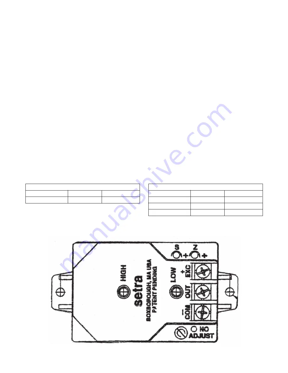
To Calibrate the Building Pressure Transducer
(PT-13)
1. Remove the tubes at the Low and High pressure
fi
ttings.
2. The voltage at –COM and OUT should be 2.5 VDC.
If not adjust Z (do not adjust S).
3.
Make sure the Low and High fi ttings are clean
and clear (do not insert any sharp objects into
the pressure fi ttings). Make sure the tubing is
also clean, clear of any debris and then reinstall
the tubes on the transducer. It is very important
that the High tube be placed inside the building,
and positioned so that air movement does not
affect it. The Low side should be to atmosphere,
and positioned so it is not exposed to the
weather.
4. With the use of a BACview 6 (KP-01) place the
unit in the Building Pressure mode. (See the Digital
Control System User Manual).
5. The voltage at –COM and OUT will vary between
0 to 5 VDC. O VDC means the building is in a
negative pressure and should open the Outside
Air/Pro
fi
le and close the Return Air damper. 5 VDC
means the building is in a positive pressure and
should open the Return Air Damper and close the
Outside Air/Pro
fi
le Damper.
To calibrate the Flow Station Pressure Transducer
(PT-15)
1. Remove the tubes at the Low and High pressure
fi
ttings.
2. The voltage at –COM and OUT should be O VDC.
If not adjust Z (do not adjust S).
3.
Make sure the Low and High fi ttings are clean
(do not insert any sharp objects into the
pressure fi ttings) make sure the static pressure
sensing pitot tubes and all tubing is also clean,
clear of any debris and then reinstall the tubes
on the transducer. It is very important that
the Low and High tubes from the Flow Station
are installed on the transducer correctly (see
drawing #C000643 below).
4. With the use of a BACview 6 (KP-0l) place the unit
in the Calibration Mode (see the Digital Control
System User Manual). This will open the Return Air
damper and close the Outside Air damper. The unit
will calibrate for 5 minutes.
IMPORTANT: Be sure
there is no blockage in the return air duct.
5. The voltage at –COM and OUT should be at least
2 VDC. If the voltage is less than 2 VDC contact the
factory.
SETRA P/N
26510R1WBABT1C
MESTEX P/N
68.0330.69
RANGE
± .1 IN WC
PT-13
PT-15
SETRA P/N
26510R1WDABT1C
2651R25WDABT1C
26510R5WDABT1C
MESTEX P/N
68.0330.66
68.0330.67
68.0330.68
RANGE
0 - 0.1 IN WC
0 - .25 IN WC
0 - .5 IN WC
TROUBLESHOOTING GUIDE


