Appleton • 1.800.621.1506 • www.appletonelec.com
303302 Rev. G 02/16 • Page 8 of 12
Service
WARNING
Electrical power must be turned OFF before and during installation and maintenance. Failure to do so may result in serious or fatal
injuries due to electrocution.
WARNING
If any part of the receptacle appears to be missing, broken, or show signs of damage—discontinue use immediately! This condition
could cause serious or fatal personal injury due to electrocution and/or equipment damage. Repair with the proper replacement part(s)
before continuing service.
Disconnect Switch
Disconnect switches occasionally fail and need to be replaced. The disconnect switch used in this receptacle can be replaced with the
same type and brand as factory installed and will not affect the UL Listing.
To replace the disconnect switch:
1.
Referring to Figures 2 and 4, remove the switch actuating fork (Item #10) by loosening the switch actuator screws (Item #11).
2.
Loosen the line side pressure screws (Item #7) and remove the line side wires from the disconnect switch (Item #13).
3.
Remove the disconnect switch by taking out the switch mounting screws (Item #12). Remember the orientation of the “arrow” on
receptacle collar with respect to the switch position. The “arrow” must indicate that the receptacle is OFF when the disconnect
switch is in the “OFF” position.
4.
Take the disconnect switch out of the enclosure. Loosen the load side pressure screws (Item #9) and remove the load side wires.
5.
Replace the disconnect switch with the same type as shown in Table 5 and reverse the steps above. Make sure to reconnect the
wires to the same locations as before disassembly.
Table 5: Disconnect Switch
Disconnect Switch Part Number
Ampere Ratings
Number of Poles
Appleton
Leviton
Hubbell/Bryant
59501735000
MS303-DS
HBL7810D/30003D
30
3
59301608001
---
HBL7863FWD/60003FWD
60
3
6.
Torque the switch mounting screws to 20–25 in.- lb. to fasten the disconnect switch inside the enclosure (Item #5).
7.
Torque the line and load pressure screws to 25 in.- lb. for 30 A or 35 in.- lb. for 60 A to hold the wires in place.
8.
Conduct electrical tests. Refer to “Electrical Testing” on page 6 for details.
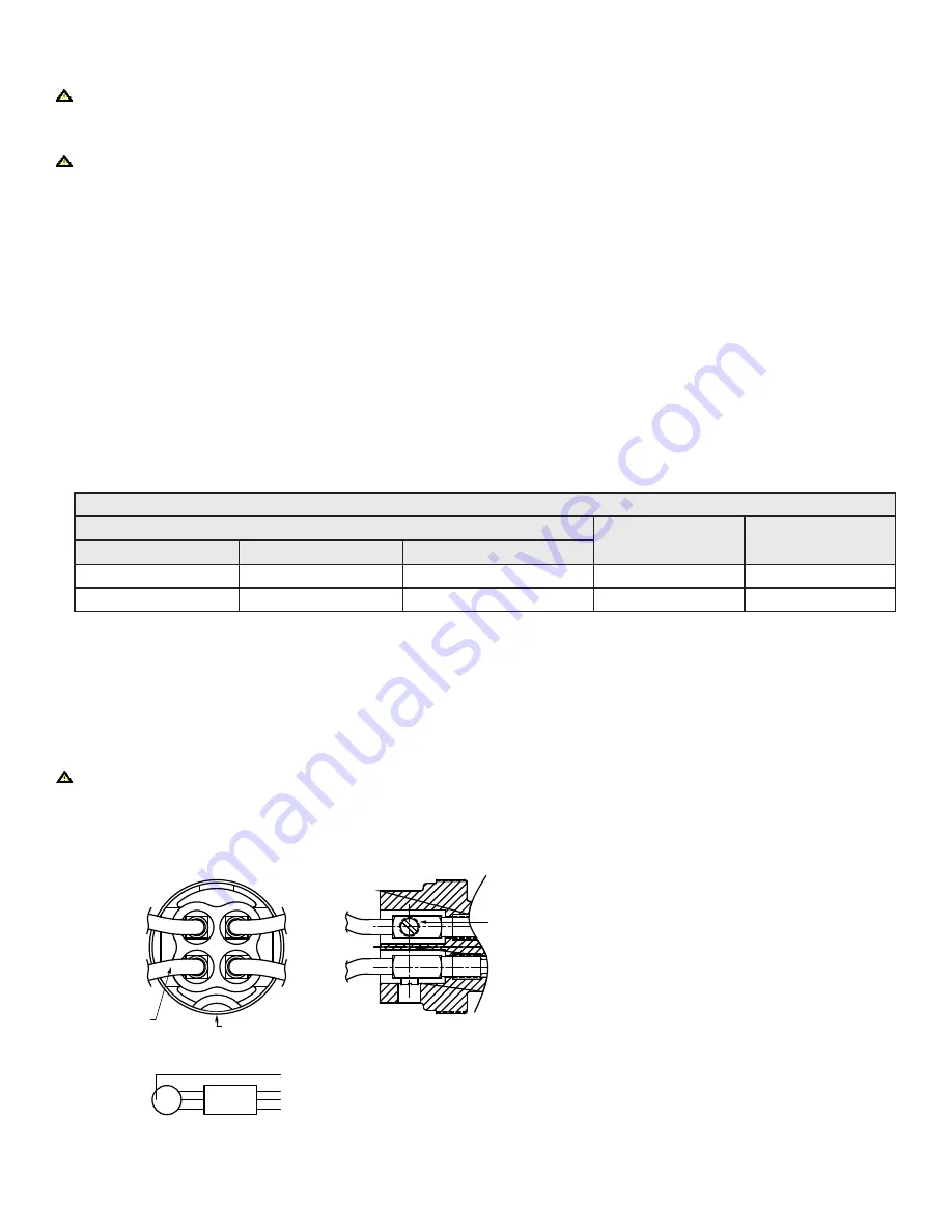
Terminal Block Interior
If applicable, tighten the terminal block lug screws to 40–45 in.-lb. torque for #6–#2 AWG wire range or 35–40 in.-lb. torque for #14–#6
AWG wire range.
WARNING
Failure to tighten the terminal block lug screws to the above torque values may result in over stressed wire terminations, which could
cause the conductors to pull out of the terminal block and cause serious/fatal injuries due to electrocution.
Figure 5: Receptacle Phase Designation—3 Wire, 4 Pole
G
GROUNDING WIRE
GROUNDING WIRE
1
3
2
HALF MOON
CONFIGURATION
TERMINAL BLOCK
LUG SCREW


