Appareo Stratus 2i Installation Manual Download Page 4


600840-000033 Stratus 2i Installation Guide 

Revision 2.0 

Last Revised: September 5, 2017


Page 4 of 7 


3. 

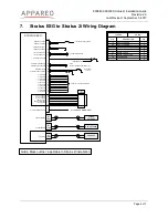
Installing the interface cables 

NOTE:

 For instructions on installing Stratus ES/ESG, reference the Stratus ES/ESG Installation 

Instructions (Appareo document number 600840-000031 for TSO installations and 
600840-000032 for STC installations). These documents can be found on the Aviation Dealer 
Portal.  
 

1.  Wire the 9 pin D-Sub connector to the transponder following the wiring diagram on 

Page 5, allowing for a maximum harness length of 3 feet. Use 20 gauge wire for this 
harness. 

2.  Mate this 9-pin D-Sub connector with the Stratus 2i power serial interface cable and 

secure using the thumb screws. 

3.  Attach the BNC blind mate adapter to the ADSB AUX hole on the transponder backplate. 
4.  Attach the BNC connector of the Stratus 2i RF interface cable to Stratus ES/ESG’s 

ADSB AUX port. 

5.  Connect the remaining end of the power serial cable into the power port of Stratus 2i 

(marked by the power symbol).  

6.  Connect the remaining end of the Stratus 2i RF interface cable into the ADS-B port of 

Stratus 2i. Secure cables as necessary. 

7.  Power on the aircraft to ensure that Stratus 2i is receiving power. Refer to the LED 

indicator statuses on Page 7. 


4. 

Configuring the transponder 

The transponder must be configured to allow for ADS-B In receiver information from the cockpit 
after Stratus 2i has been placed in the aircraft. 
 

1.  Enter into configuration mode on the transponder (while holding the 

FUNC

 key, press 

and release the 

PWR

 key). 

2.  Press 

FUNC

 or the arrow keys to navigate to the “ADS-B Capability” screen and press 

ENT

3.  Use the arrow keys to set the capability to 

UAT

 and 

1090 ES

 (the frequencies Stratus 2i 

is capable of).  

4.  Press 

ENT


5. 

Powering receiver on and off 

Once it is receiving aircraft power, Stratus 2i will automatically turn on. All LED indicators will 
briefly illuminate red and then green as the receiver powers on and auto-calibrates. If Stratus 2i 
is moved after being turned on, it must be re-calibrated in ForeFlight Mobile. 
 

Summary of Contents for Stratus 2i

Page 1: ...Stratus 2i Installation Guide Revision 2 0 ...

Page 2: ...in this guide Unauthorized replication of this guide is prohibited Appareo Appareo Systems Stratus and the Appareo logos are either registered trademarks or trademarks of Appareo Systems LLC MITRE is a registered trademark of the MITRE Corporation iPad iPhone and iPod touch are registered trademarks of Apple Inc App Store is a service mark of Apple Inc All other trademarks and registered trademark...

Page 3: ...F interface cable 9 pin D Sub connector with mounting hardware BNC jack to blind mate adapter 2 Placing Stratus 2i in the aircraft Choose an installation location that provides for the best line of sight between the Stratus 2i and the iPad for optimal Wi Fi communication It is important for Stratus 2i to be installed in the orientation indicated by the Direction of Flight arrow on the receiver Str...

Page 4: ...power serial cable into the power port of Stratus 2i marked by the power symbol 6 Connect the remaining end of the Stratus 2i RF interface cable into the ADS B port of Stratus 2i Secure cables as necessary 7 Power on the aircraft to ensure that Stratus 2i is receiving power Refer to the LED indicator statuses on Page 7 4 Configuring the transponder The transponder must be configured to allow for A...

Page 5: ...XTERNAL IDENT EXTERNAL SQUAT SWITCH ALTITUDE A1 ALTITUDE A4 ALTITUDE B2 ALTITUDE C1 ALTITUDE C4 ALTITUDE D4 ALTITUDE A2 ALTITUDE B1 ALTITUDE B4 ALTITUDE C2 AUX 5V POWER AUX 5V POWER AUX 5V POWER RS232 TX AUX RS232 TX GPS 1PPS ALTITUDE COMMON GND XPNDR ANTENNA GPS ANTENNA IN STRATUS ESG ONLY ADS B AUX 2 21 1 20 15 33 7 14 32 3 18 25 26 9 10 11 12 13 27 28 29 30 31 19 36 17 23 6 37 11 33 VDC AIRCRAF...

Page 6: ...ERNAL IDENT EXTERNAL SQUAT SWITCH ALTITUDE A1 ALTITUDE A4 ALTITUDE B2 ALTITUDE C1 ALTITUDE C4 ALTITUDE D4 ALTITUDE A2 ALTITUDE B1 ALTITUDE B4 ALTITUDE C2 AUX 5V POWER AUX 5V POWER AUX 5V POWER RS232 TX AUX RS232 TX GPS 1PPS AUX GROUND ALTITUDE COMMON GND XPNDR ANTENNA GPS ANTENNA IN ADS B AUX 2 21 1 20 15 33 7 14 32 25 26 9 10 11 12 13 27 28 29 30 31 19 36 17 23 6 18 37 11 33 VDC AIRCRAFT POWER 5A...

Page 7: ...ellow ADS B FIS B signal has been received from one tower in the past three seconds Off ADS B FIS B signal has not been received in the past three seconds All indicators Briefly red and then green Receiver is powering on and calibrating Red flashing Built in test failure Contact support for assistance Yellow flashing Installing firmware update Yellow solid Applying firmware update Green for two se...

Reviews: