ASSEMBLY
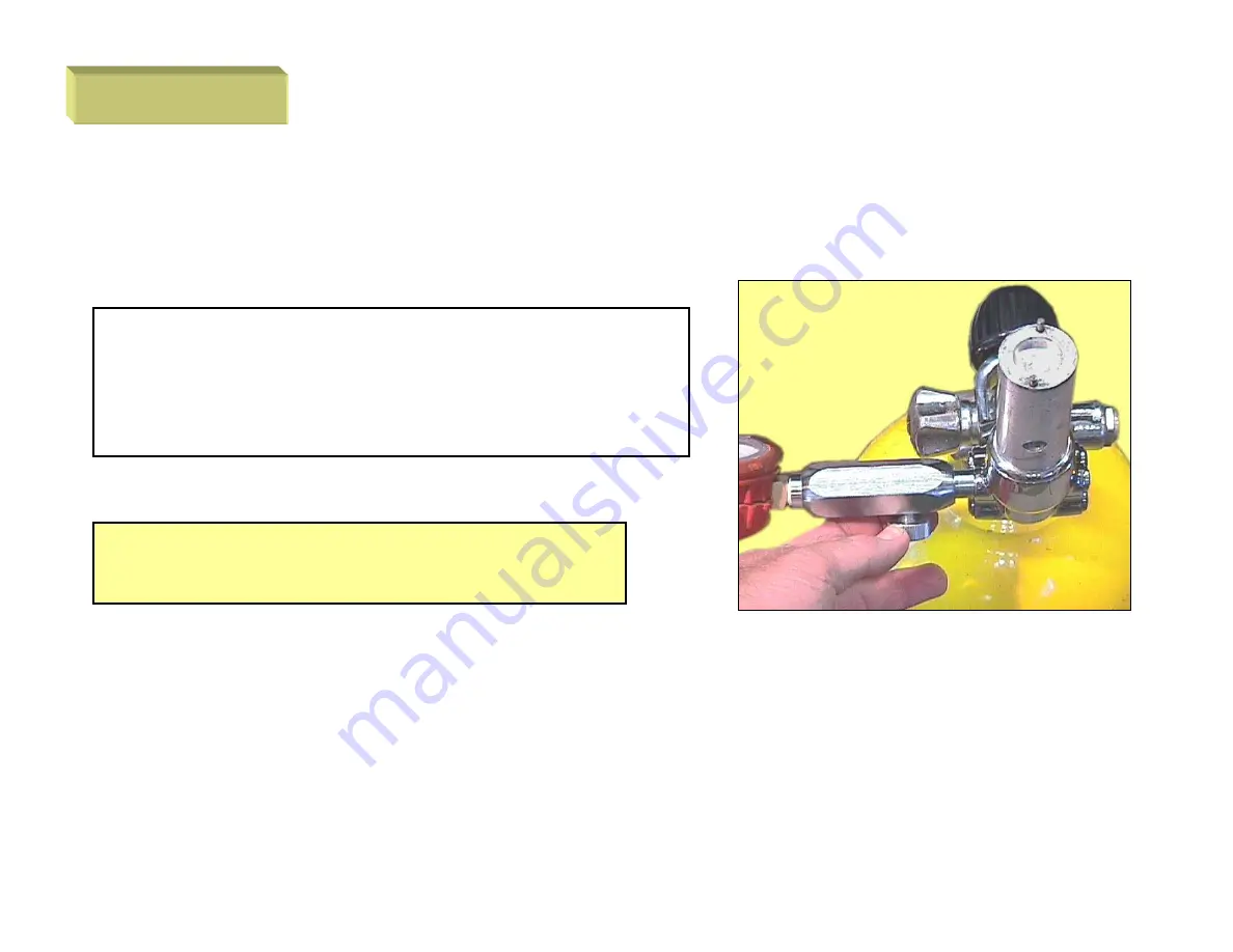
The Apollo test gauge has a bleed screw,this should be slightly open when turningthe air on. Once the system is pressurisedtighten the bleed screw.
NOTE: Ensure all the ports areblanked to carry out the adjustments.
Page 1: ...A 102 1ST STAGE DISASSEMBLY...
Page 2: ...FEATURES FEATURES Balanced Diaphragm type 1st stage 2 x HP port 7 16 NF 4 x LP port 3 8 NF Lightweight and compact Symmetrical service ports...
Page 3: ...0 3 16 5 8 Allen key wrench Snap ring circle pliers O ring pick Fine tweezers Nylon dowel 10mm dia Small screw driver blunt edges Threaded rod 7 16 NF handle Engineers vice with soft jaws Line pressur...
Page 4: ...MBLY Remove the yoke screw To support the 1st stage fit the 7 16 threaded rod to a HP port and hold the rod in a suitable vice Use a 12 adjustable wrench undo the yoke retainer The retainer is removed...
Page 5: ...DISASSEMBLY DISASSEMBLY Remove the yoke and yoke retainer Strip the yoke retainer ready for cleaning and inspection Remove the yoke bolt o ring...
Page 6: ...DISASSEMBLY DISASSEMBLY Carefully remove the filter retaining ring Remove and discard the filter...
Page 7: ...DISASSEMBLY DISASSEMBLY Fit the Apollo adjusting wrench to the body cap Use a 12 adjustable wrench undo and lift off the body cap to expose the adjusting assembly Turn anti clockwise to undo...
Page 8: ...DISASSEMBLY DISASSEMBLY Lift off the teflon washer and place to one side Lift out the adjusting screw and guide nut...
Page 9: ...DISASSEMBLY DISASSEMBLY Separate the screw and nut the screw is left hand thread Next lift out the LP spring and the spring pad...
Page 10: ...DISASSEMBLY DISASSEMBLY Install the Apollo adjusting wrench Engage the pins in the diaphragm retainer Use the 12 adjustable wrench and undo the diaphragm retainer turning counter clock wise...
Page 11: ...DISASSEMBLY DISASSEMBLY Lift out the diaphragm retainer Carefully remove the diaphragm washer...
Page 12: ...s use air pressure to lift the diaphragm off its seat Apply pressure gently and place a rag over the top of the body to prevent the diaphragm from being blown out and possibly causing an injury Remove...
Page 13: ...ly and place to one side The HP module is removed next Use a wide blade screw driver to avoid damaging the groove NOTE If the HP module is tight and appears to be locked in position refer to HP Module...
Page 14: ...sure with your thumb or finger while engaging the circlip pliers to the retaining ring DISASSEMBLY While compressing the retaining ring gradually reduce the downward pressure The HP assembly should no...
Page 15: ...ve from the chamber and discard DISASSEMBLY After removing the o ring check the teflon back up ring for damage Any signs of damage scoring etc is cause for rejection in this case a new balance chamber...
Page 16: ...A 102 1ST STAGE INSPECTION ASSEMBLY...
Page 17: ...e diluted using water however diluting usually only means a longer soak period before the parts are clean Only leave the parts in the vinegar bath until clean do not leave in the bath for prolonged pe...
Page 18: ...fice cone for damage prior to assembly The pushrod assembly must be inspected for corrosion on the shaft also any bending of the shaft If any damage is noted replace the shaft All threads are checked...
Page 19: ...ng all o rings are to be carefully inspected for damage or distortion If the HP seat is to be reused for a repair replace for a service carefully inspect the rubber face for ANY defects Deep witness m...
Page 20: ...ator approved for use with Nitrox or O2 enriched Breathing Air Other procedures NOT covered by this manual MUST be carried out prior to use with mixed gases other than standard air STATIC O RINGS Must...
Page 21: ...ring by using your fine tweezers as shown Be sure to fit the o ring between the white teflon back up ring and the brass washer The o ring must sit between the two parts not on top of the brass washer...
Page 22: ...ASSEMBLY ASSEMBLY Next place the HP spring onto the seat Place the balance chamber onto the spring the side with the o ring facing the seat and spring...
Page 23: ...Sit the retaining ring on top of the assembly Ensure all parts are centred or you will have difficulty compressing the assembly and installing the retaining ring Compress the HP assembly and install t...
Page 24: ...aining ring for security be sure to wear eye protection and never point the assembly directly at your face CAUTION Check to ensure the retaining ring is located correctly in its groove Lubricate and i...
Page 25: ...very lightly if at all and install the module assembly Using a thick bladed screw driver screw the module into position DO NOT tighten down hard Tighten until the module bottoms and then back out appr...
Page 26: ...ntre of the HP seat Depress the assembly several times with your thumb to test the movement of the seat assembly ASSEMBLY Next install the diaphragm Bend between thumb and forefinger to make the insta...
Page 27: ...ASSEMBLY ASSEMBLY Use your nylon drift or your finger to push the diaphragm flat all the way around against the inner shoulder The diaphragm washer is placed on top of the diaphragm...
Page 28: ...ASSEMBLY ASSEMBLY The spring pad is dropped through the retainer Ensure the flat side is down recessed side up Lightly lubricate both ends of the spring and then install onto the spring pad...
Page 29: ...ner with a Christo lube or silicone grease and install the retainer The retainer must be finally tensioned using a spanner with the Apollo tool Tighten sufficiently to ensure no leakage of air from un...
Page 30: ...SEMBLY ASSEMBLY Lightly lubricate the thread of the adjusting shaft and screw onto the nut left hand thread Screw the nut onto the shaft until almost touching Ensure the recess side is facing the spri...
Page 31: ...ASSEMBLY ASSEMBLY Place the teflon washer onto the adjusting shaft nut Place the body cap over the spring adjusting assembly Hand tighten...
Page 32: ...ASSEMBLY ASSEMBLY Tighten the body cap using the Apollo adjusting wrench Slightly more than hand tight is sufficient Sit the filter into the yoke retainer Coarse or rough side of the filter faces up...
Page 33: ...ing ring Ensure the retaining ring is seated correctly in its groove Lightly lubricate the yoke retainer o ring and fit to its groove Examine this o ring carefully before reusing Any signs of distorti...
Page 34: ...NOTE DO NOT lubricate the yoke retainer thread A small drop of Loctite 243 can be applied to the thread This will ensure the yoke does not come loose during service Place the yoke and retainer assemb...
Page 35: ...yoke retainer using the 12 adjustable wrench Lightly lubricate and install the yoke screw not shown Attach the Apollo low pressure test gauge to a low pressure port Fit the 1st stage to a source of hi...
Page 36: ...Y The Apollo test gauge has a bleed screw this should be slightly open when turning the air on Once the system is pressurised tighten the bleed screw NOTE Ensure all the ports are blanked to carry out...
Page 37: ...n clockwise to increase pressure counter clockwise to decrease the pressure When decreasing pressure remember to open and close the bleed screw to obtain the correct pressure reading Adjust the pressu...
Page 38: ...ASSEMBLY ASSEMBLY The first stage is now ready for service A final check for leakage can be carried out after the installation of the 2nd stage and any accessories BC hose etc...