Apogee AMBus HD User Manual Download Page 13

APOGEE ELECTRONICS

5

AMBus HD card

 – User’s Guide

Digilink Connections

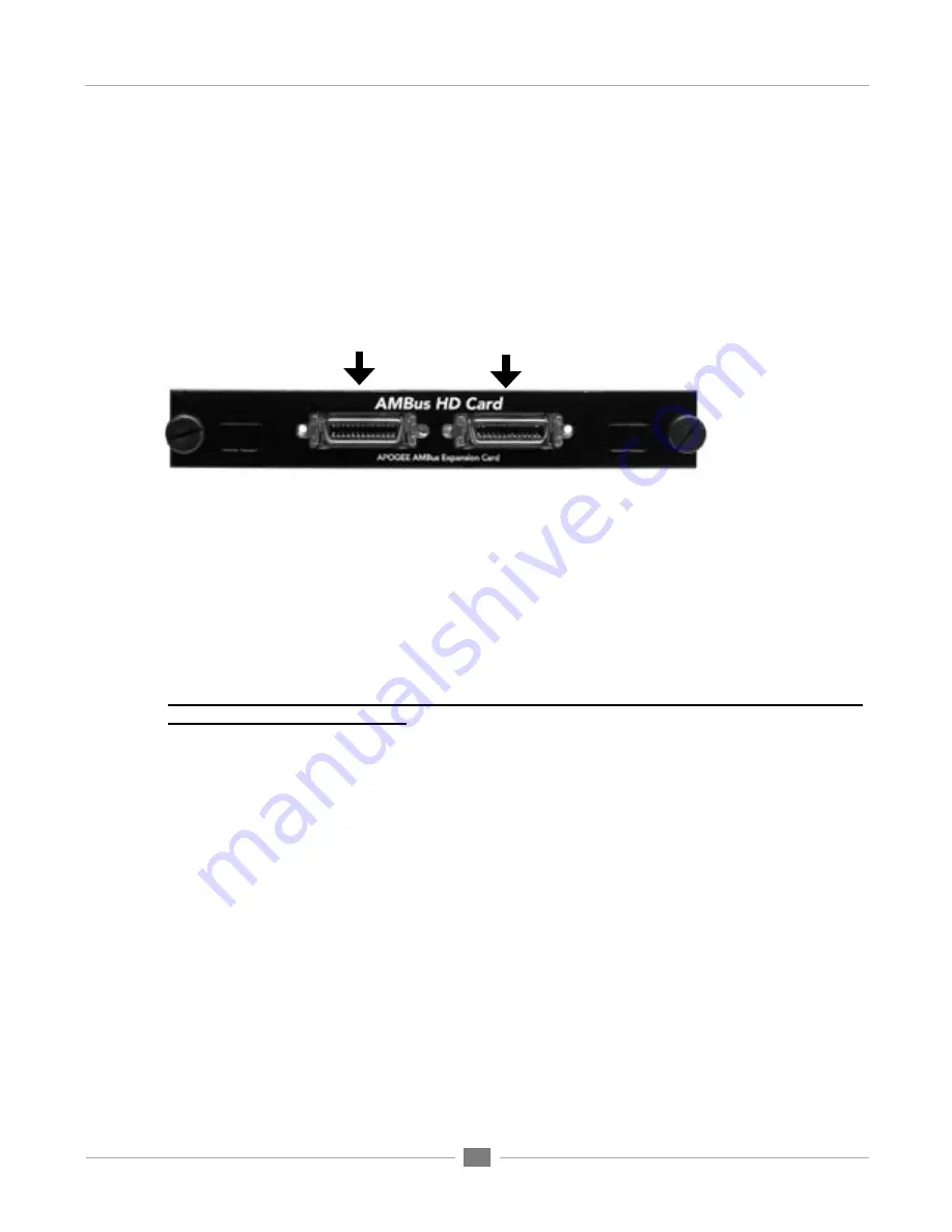
Like Digidesign interfaces, the AMBus HD card is equipped with two ports, Primary and Expansion. 

Please note that the Primary Port on the AMBus HD card is the LEFT connector when looking from 
the back of the unit.

The proper order to connect Apogee, Digidesign and Prism hardware interfaces may be determined 
by locating the entry on pages


13-14  that corresponds to the set of interfaces you wish to connect. 

When using Digidesign or Prism interfaces, please note that they must be connected first in the 
Digilink chain.

Connect a Digilink cable from the HD Core, Process or Accel card to the Primary port on interface #1, 
from interface #1’s Expansion port to interface #2’s Primary port, from interface #2’s Expansion port to 
interface #3’s primary port, and so on until all interfaces are connected. 

Use only 18” Digilink cables 

to make connections between hardware interfaces.

After all clock and Digilink connections have been made, ensure that all devices are locked to a valid 
clock before booting the computer.

this is the 

PRIMARY 

PORT

this is the 

EXPANSION 

PORT

Summary of Contents for AMBus HD

Page 1: ...User s Guide V1 0 March 2005 Apogee AMbus Expansion Card...

Page 2: ......

Page 3: ...User s Guide V1 0 March 2005 Apogee AMbus Expansion Card...

Page 4: ...r measures necessary to correct the interference at his own expense Copyright Notice The Apogee AMBus HD card is a computer based device and as such contains and uses software in ROMs This software an...

Page 5: ...which the receiver is connected 4 Consult the dealer or an experienced radio TV technician for help NOTE The use of non shielded cable with this equipment is prohibited CAUTION Changes or modi cations...

Page 6: ...upgrade to existing units This warranty is void if Apogee determines in its sole business judgment the defect to be the result of abuse neglect alteration or attempted repair by unauthorized personne...

Page 7: ...____________________________________ Dealer_________________________________________________________________ Phone_________________________________________________________________ Address_____________...

Page 8: ......

Page 9: ...rted Quickly Connecting AMBus HD equipped Apogee Interfaces Incorporating a Sync I O Clock Con gurations Digilink Connections Con guring Digidesign Pro Tools Hardware Setup I O Setup Interface Connect...

Page 10: ...on this page is general information on connecting Digilink connections once the proper order has been determined Please note that the Primary Port on the AMBus HD card is the LEFT connector when looki...

Page 11: ...ration using BIG BEN In lieu of Big Ben we recommend connecting the master device s clock output to the slave devices using BNC T connectors as illustrated in the connection diagrams shown to the righ...

Page 12: ...d clock inputs of the audio interfaces for jitter attenuation HD equipped Apogee interface as master SYNC I O slave Due to automatic switch ing of clock sources in Pro Tools it is not practical to loc...

Page 13: ...sh to connect When using Digidesign or Prism interfaces please note that they must be connected rst in the Digilink chain Connect a Digilink cable from the HD Core Process or Accel card to the Primary...

Page 14: ...h each HD PCI card on the DigiLink cable while the I O Setup dialog serves to label and map the manner in which these 32 busses appear in Pro Tools software As the audio I O of Apogee interfaces diffe...

Page 15: ...hen Apogee hardware is locked to an external clock source such as Big Ben be sure to set the hardware clock rate to correspond to the session sample rate Port Settings If this parameter is not greyed...

Page 16: ...rd is in use For example three Rosetta 800s appear in the Hardware Setup as two 192 I Os but only I O channels 1 24 are used NOTE TO AMBus HD CARD USERS In the following connection charts a Rosetta 80...

Page 17: ...IN USE INPUT OUTPUT ROSETTA 800 1 ROSETTA 800 2 INPUT OUTPUT ROSETTA 800 1 ROSETTA 800 2 ROSETTA 800 3 ROSETTA 800 4 A1 16 B1 16 A1 16 B1 16 A1 16 B1 16 A1 16 B1 16 From Computer E P E P From Compute...

Page 18: ...16X 2 ROSETTA 800 1 ROSETTA 800 2 A1 16 B1 16 A1 16 B1 16 A1 16 B1 16 A1 16 B1 16 APPEARS AS in Hardware Setup From Computer E P E P E P From Computer E P E P E P E P From Computer E P E P From Compu...

Page 19: ...Computer E P E P E P INPUT OUTPUT AD 16X 1 ROSETTA 800 1 A1 16 B1 16 From Computer E P APPEARS AS in Hardware Setup INPUT OUTPUT AD 16X 1 DA 16X 1 ROSETTA 800 1 ROSETTA 800 2 A1 16 B1 16 From Computer...

Page 20: ...From Computer E P E P E P From Computer E P E P INPUT OUTPUT DIGI 192 1 DA 16X 1 A1 16 B1 16 INPUT OUTPUT DIGI 192 1 DA 16X 1 A1 16 B1 16 AD 16X 1 INPUT OUTPUT DIGI 192 1 A1 16 B1 16 ROSETTA 800 1 INP...

Page 21: ...et by Pro Tools This function is useful if an AD 8000 will be master clock for the additional interfaces In instances where an AD 8000 will be clocked via a master clock the unit must be set manually...

Page 22: ...until you feel it mate with the AMBus connector 4 Fasten the card in place with the included screws A NOTE ABOUT UPDATING THE AMBUS HD CARD Due to the space constraints associated with AMbus card slo...

Page 23: ......

Page 24: ...AMBus HD card USER S GUIDE v1 0 March 2005 Text conceived and delivered by Roger Robindore Graphics and illustrations by Sean McArthur...

Reviews: