APLICOM A9 IPEX Installation Manual Download Page 9


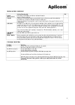
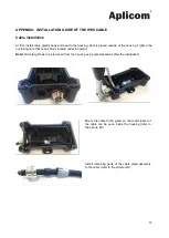
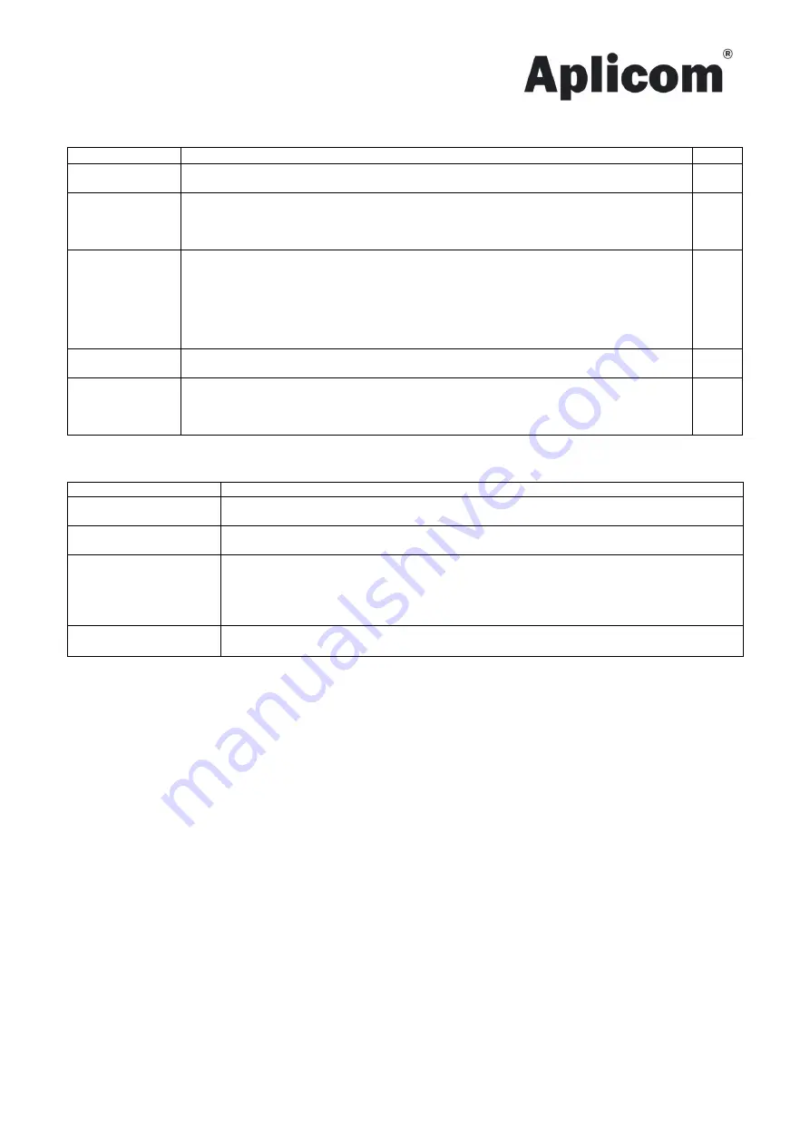
INSTALLATION CHECKLIST   


Action/Functionality 

OK 

DEVICE 
INSTALLATION 

The place of installation is safe from accidental knocks. 
Device is fastened tightly. 
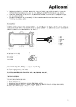
 

CABLES 

Cables are led carefully along a well-protected route to the device and the peripherals. 
All cables are correctly connected and secured with fuses. 
Cables are fastened or supported in such a way that during use they exert no torsion on the 
cable glands.  


ANTENNAS 

A9 IPEX unit is fitted in such a way that its visibility to base stations is as unobstructed as 
possible (vehicle roof; as far as possible away from other antennas, flashing lights etc.). A9 
IPEX  unit  is  fitted  in  such  a  way  that  its  satellite  visibility  is  as  unobstructed  as  possible 
(vehicle roof; as far as possible away from other antennas, flashing lights etc.). 
 
Check  the  A9  IPEX  right  orientation  towards  the  GPS/GLONASS  satellites  and  correct 
fixing place and surface. 


POWER ON 
DEVICE 

Connect PWR and if IGN is used, turn it on. 


FINAL CHECK 

Before completing the installation work, rigorous checking of any disturbances to vehicle or 
machine, where the unit is installed, must be made. Special attention is needed to check 
the vehicle safety systems and radio and multimedia equipment functions. This is to avoid 
recalls to service because of un-noticed problems. 


TROUBLE SHOOTING 


Problem 

Solution 

No power 

Check that all the cables and fuses are connected. 
PWR is connected and IGN is on (if used). 

No GPRS connection 

Check that SIM card is inserted.  
Check PIN CODE requirements. 

No GPS position 

Ensure that the top cover of the A9 IPEX has open sky view. 
 
Check interferences from other structures to GPS antenna. 
 
NOTE! Electronic heated or UV-protected windshield may disturb GPS antenna sky view. 


If none of the above helps, please contact your equipment dealer for further 
assistance


Summary of Contents for A9 IPEX

Page 1: ...ports following device A9 IPEX Document code K520010 Important Please read this installation guide before the installation Aplicom Oy P O Box 33 FI 44101 Äänekoski Finland Telephone 358 10 841 9414 Business ID 0995791 7 Äänekoski Info aplicom fi www aplicom com ...

Page 2: ...Therefore we reserve the right to make changes and improvements to any of the products described in this guide without prior notice Due to these improvements the contents of this manual are subject to change without notice Aplicom Oy is not responsible for any loss of data income or any consequential damage This crossed out wheelie bin means that within the European Union the product must be taken...

Page 3: ...t by using A9 NEX TRIX data cable D337055 Figure 4 6 Close the unit and tight up four cover screws Avoid extreme torque 0 8 1 0 Nm Refer to Figure 5 on how to install the top cover correctly Please follow this instruction because otherwise there is risk that the antenna connector will broke 7 Connect external power cabling and other needed connections 8 Mechanically install the unit to carefully s...

Page 4: ...larly with remaining two corners Mechanical Installation Note that the unit includes internal GPRS and GPS antennas and shouldn t be installed in metal cage Because of the internal GPS GLONASS antenna install unit to place where unit s top cover has the best possible open sky view ...

Page 5: ...ection could break down Electrical Installation Read warnings chapter on page 7 on this document Protect power supply lines 6 8 32Vdc with 3A fuse at power supply end of line Install the A9 IPEX unit as far away as possible minimum 1 metres recommended from the car radio and its antenna or other electrical devices to avoid any interference Additional information Application note K505002 Cabling of...

Page 6: ...ered and wire nr 1 is connected to screw connector position 1 as default and wire 2 is connected to position 2 and so on The used cable has seven wires Figure 8 1 GND 2 PWR 3 IGN DIN1 4 DIN2 5 OC 6 CANH 7 CANL Used to SW configuration COM1 port sw option and SW debug Note Use only Aplicom specific cable Note When using this cable the unit has to be open top cover removed Testing installation If th...

Page 7: ... 2 1077 a 3 The identification by name address and telephone number or Internet contact information of the responsible party as defined in 2 909 The responsible party for Supplier s Declaration of Conformity must be located within the United States For FCC Part 15 devices 15 19 a 3 This device complies with Part 15 of FCC rules Operation is subject to the following two conditions 1 this device may...

Page 8: ...empt RSS s Operation is subject to the following two conditions 1 This device may not cause interference 2 This device must accept any interference including interference that may cause undesired operation of the device Changes or modifications not expressly approved by the party responsible for compliance could void the user s authority to operate the equipment For Canada ICES RSS L émetteur réce...

Page 9: ...PEX right orientation towards the GPS GLONASS satellites and correct fixing place and surface POWER ON DEVICE Connect PWR and if IGN is used turn it on FINAL CHECK Before completing the installation work rigorous checking of any disturbances to vehicle or machine where the unit is installed must be made Special attention is needed to check the vehicle safety systems and radio and multimedia equipm...

Page 10: ... the nut taking care that seal is firmly located under the gland Note All metal grit has to be removed from the housing using compressed air after the installation Mount the cable to the gland so that outer jacket of the cable can be seen inside the housing refer to the picture left Install remaining parts of the cable gland assembly to the cable refer to the picture left ...

Page 11: ...use the threadlocker in the thread of the cable gland to secure the assembly Suitable threadlocker type is medium strength type like Würth 0893243050 or equivalent Tighten the nut with the help of the suitable feeler gauge which thickness depends on used interface cable For standard IPEX cable the thickness of the feeler gauge is 2mm Make sure that feeler gauge is removable after tightening the nu...

Reviews: