ARMPAC-6XX(AL) Series User Manual
23
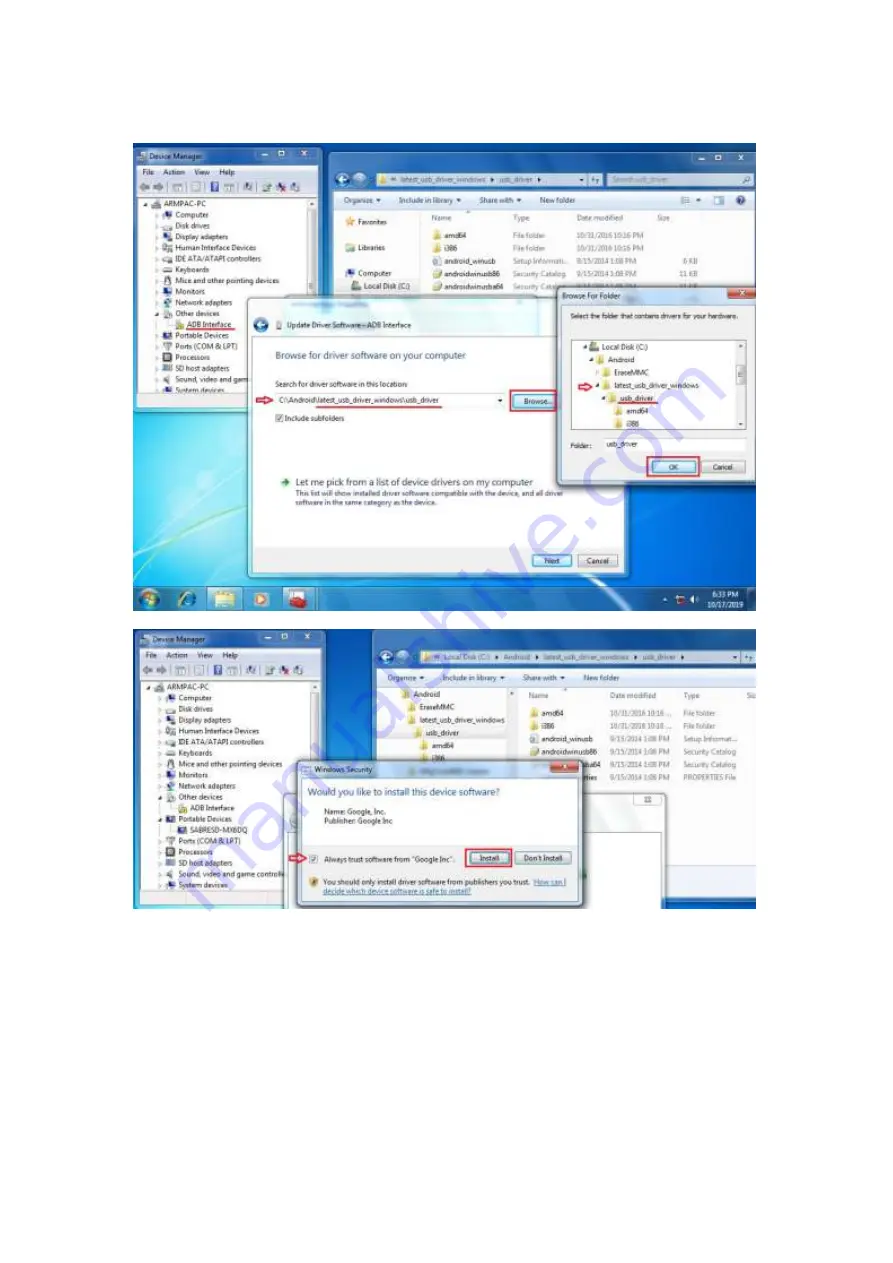
4)
Click “Browse” to \lastest_usb_driver_windows\usb_driver\.
Page 1: ...ARMPAC 6XX AL 15 15 6 and 21 5 Fanless i MX6 DualLite ARM Cortex A9 HMI Series User Manual Release Date Revision Oct 2019 V1 5 ...
Page 2: ...Official Version 1 1 2017 10 20 Add motherboard version Add 15 15 6 Modify software IP rating 1 2 2018 11 09 Delete all QTs data Update OS Support list 1 3 2019 02 19 Revise pin9 information 1 4 2019 03 18 Update Storage Temperature 1 5 2019 10 18 Update Linux and ANDROID information and photos ...
Page 3: ...anual it may cause interference to radio communications It has been tested and found to comply with the limits for a Class A computing device pursuant to FCC Rules which are designed to provide reasonable protection against such interference when operated in a commercial environment Operation of this equipment in a residential area is likely to cause interference in which case the user at his own ...
Page 4: ...ARMPAC 6XX AL Series User Manual 3 Packing List Accessories as ticked included in this package are Adaptor Driver manual CD disc Other ___________________ please specify ...
Page 5: ...icity on all occasions Prevent electric shock Don t touch any components of this card when the card is power on Always disconnect power when the system is not in use Disconnect power when you change any hardware devices For instance when you connect a jumper or install any cards a surge of power may damage the electronic components or the whole system ...
Page 6: ...6 Panel Mounting 11 Chapter 2 Hardware 2 1 Motherboard Jumpers Setting and Connectors 12 Chapter 3 Software images 3 1 Update Linux for SBC 7112 18 3 2 Update Android Firmware 21 Figures Figure 1 1 Dimensions of ARMPAC 615 P 8 Figure 1 2 Dimensions of ARMPAC 616 P 8 Figure 1 3 Dimensions of ARMPAC 621 P 9 Figure 1 4 Front View of ARMPAC 6XX AL 10 Figure 1 5 Rear View of ARMPAC 6XX AL 10 Figure 1 6...
Page 7: ... 621 P System CPU Freescale i MX6 DualLite Quad option ARM Cortex A9 processor 1 0GHz Memory Onboard 1GB DDR3 DRAM External IO Port USB 2 x USB 2 0 type A 1 x USB 2 0 Micro B type Serial Parallel 1 x RS 232 422 485 DB 9 COM1 LAN 1 x LAN Port Power 1 x 9 36V DC power input via 1 x 3 pin terminal block for 15 15 6 1 x 12 36V DC power input via 1 x 3 pin terminal block for 21 5 Option 1 x RS 232 422 ...
Page 8: ...sion Over 80 Touch Screen Projected Capacitive Type Interface USB Light Transmission Over 90 Power Power Input DC 9 36V DC 12 36V Power Consumption MAX 11 1W MAX 13 7W MAX 20 5 W Mechanical Front Bezel Metal Flat Bezel design Rear Panel Metal ALU VESA 100 Chassis Color RAL9007 IP Rating IP66 Front Panel Dimensions 410 x 310 x 54 67 mm 412 x 277 5 x 58 9 mm 557 x 362 x 64 8 mm Net Weight 4 5 kg 4 2...
Page 9: ...ARMPAC 6XX AL Series User Manual 8 1 3 Dimensions Figure 1 1 Dimensions of ARMPAC 615 P Figure 1 2 Dimensions of ARMPAC 616 P ...
Page 10: ...ARMPAC 6XX AL Series User Manual 9 Figure 1 3 Dimensions of ARMPAC 621 P ...
Page 11: ...rd memory and 4GB eMMC NAND flash onboard There are powered by DC 9 36V for 15 and 15 6 but DC 12 36V for 21 5 wide range power input These models supports IP66 compliant front panel This model can be VESA 100 x 100 mounted The chassis color is RAL9007 for aluminum Optional projected capacitive touch screen supports 7H anti scratch surface is ideal for use as PC based controller for industrial aut...
Page 12: ...y place the unit through the hole and tighten the given screws from the rear to secure the mounting Figure 1 6 ARMPAC 6XX AL VESA Mounting 1 6 Panel Mounting There are four holes located along the four sides of the HMI Insert the clamp from the four sides and tighten them with the nuts provided Figure 1 7 ARMPAC 6XX AL Panel Mounting ...
Page 13: ...t port is provided Used Atheros AR8031 chipset support LINK LED green and ACTIVE LED yellow 4 MIO1 1 25mm Pitch 2 15 Connector Including eight General purpose input output a group of SMBUS and two groups of serial communication interfaces it provides a group of self programming interfaces to customers for flexible use Signal Name Pin Pin Signal Name PWRON 1 2 GND POR_B 3 4 GND 5V_S0 5 6 GND GPIO_I...
Page 14: ...3 TXD3_422RX 4 DTR3_422RX 5 GND 6 NC 7 NC 8 NC 9 COM3_9PIN connect to JP1 6 CON2 2 0mm Pitch 2 8 Pin Socket it provides a group USB2 0 SMBUS UART and CANBUS interfaces Signal Name Pin Pin Signal Name 5V_S0 1 2 NC USBDN_CON2_DM3 3 4 UART4_TXD USBDN_CON2_DP3 5 6 UART4_RXD GND 7 8 GND GND 9 10 CAN1_TX I2C2_SDA 11 12 CAN1_RX I2C2_SCL 13 14 NC 3P3V_S0 15 16 NC 7 CON1 TF Card Socket Support TF Card devi...
Page 15: ...DS0 GND 3 4 GND LVDS0_TX0_N 5 6 LVDS0_TX0_P LVDS0_TX1_N 7 8 LVDS0_TX1_P LVDS0_TX2_N 9 10 LVDS0_TX2_P NC 11 12 NC LVDS0_CLK_N 13 14 LVDS0_CLK_P GND 15 16 NC BKLT_CTRL0 17 18 BKLT_EN_OUT0 VCC_BL0 19 20 VCC_BL0 11 LVDS2 1 25mm Pitch 2 10 Connector DF13 20DP 1 25V For 18 24 bit LVDS1 output connector Signal Name Pin Pin Signal Name VCC_LVDS1 1 2 VCC_LVDS1 GND 3 4 GND LVDS1_TX0_N 5 6 LVDS1_TX0_P LVDS1_...
Page 16: ...ector for LVDS1 Pin Signal Name 1 VCC_BL0 2 VCC_BL0 3 GND 4 GND 5 BKLT_EN_OUT0 6 BKLT_CTRL0 13 BT1 1 0mm Pitch 1 2 box Pin Header 3 0V Li battery is embedded to provide power for RTC Pin Signal Name 1 VRTC 2 GND 14 INVT2 2 0mm Pitch 1 6 box Pin Header Backlight control connector for LVDS2 Pin Signal Name 1 VCC_BL1 2 VCC_BL1 3 GND 4 GND 5 BKLT_EN_OUT1 6 BKLT_CTRL1 ...
Page 17: ...e 1 2 COM1 Pin9 NC default Close 3 4 COM1 Pin9 5V option Close 5 6 COM1 Pin9 12V option 18 J1 2 0mm Pitch 1 3 Pin Header LVDS1 jumper setting It is used to provide 3 3V or 5V voltage to VCC_LVDS0 J1 Pin Function Close 1 2 VCC_LVDS0 3 3V option Close 2 3 VCC_LVDS0 5V default 19 J2 2 0mm Pitch 1 3 Pin Header LVDS1 jumper setting It is used to provide 5V or 12V voltage to VCC_BL0 J2 Pin Function Clos...
Page 18: ...l Switch it is used to select the voltage for BKLT_CTRL0 and BKLT_EN_OUT0 SW2 Pin Function Function 1 4 Close Open default BKLT_CTRL0 3 3V BKLT_CTRL0 5V 2 3 Close Open default BKLT_EN_OUT0 3 3V BKLT_EN_OUT0 5V 23 SW3 Dial Switch it is used to select the voltage for BKLT_CTRL1 and BKLT_EN_OUT1 SW3 Pin Function Function 1 4 Close Open default BKLT_CTRL0 3 3V BKLT_CTRL0 5V 2 3 Close Open default BKLT...
Page 19: ...es User Manual 18 Chapter 3 Software images 3 1 Update Linux for SBC 7112 1 Close Chromium Browser and return to desktop then select the Terminal APP 2 Key in below command to erase the EMMC data change to Download Mode ...
Page 20: ...ct Micro USB Cable from SBC 7112 to your desktop laptop and run update tool Linux 4 9 88 eMMC MX6DL ALL vbs 4 It will show up Hub X Port Y on the upper left side if USB cable has been connected well and then click Start to update Linux Firmware ...
Page 21: ... User Manual 20 5 When you finish updating the screen will show the increasing counting numbers of Successful Operations Click Stop and Exit then reset machine 6 Linux 4 9 88 Chromium Browser have been updated successfully ...
Page 22: ...r Windows 7 The USB driver should be connected to VITAM 6XX device 2 File2 EraseMMC zip Erase all data on Flash and switch to download mode before updating Android firmware 3 File3 MfgtoolA601_master zip Update Android Firmware update utility Step 1 File1 latest_usb_driver_windows zip ADB Interface Driver for Windows 7 1 Install ADB Interface Driver for Windows 7 laster_usb_driver_windows zip ...
Page 23: ...ARMPAC 6XX AL Series User Manual 22 2 Double click ADB Interface to Update Driver 3 Select Browse my computer for driver software to locate and install driver software ...
Page 24: ...ARMPAC 6XX AL Series User Manual 23 4 Click Browse to lastest_usb_driver_windows usb_driver ...
Page 25: ...ARMPAC 6XX AL Series User Manual 24 5 Click Close to complete the driver installation PS Windows 10 OS Please skip step 1 ...
Page 26: ...r Manual 25 Step 2 File2 EraseMMC zip 1 Switch to Download mode Erase all data on Flash via EraseMMC bat 2 It switches to Download Mode when the screen shows like the picture below and then you can reset the machine ARMPAC 6XX ...
Page 27: ...elow picture if the USB hasn t been connected well Step 3 File3 MfgToolA601 master zip 1 Copy all images files include boot imx6dl img recovery imx6dl img system img u boot imx6dl imx into sabresd folder as below MfgToolA601 master Profiles Linux OS Firmware files android sabresd ...
Page 28: ... Android6 0 1 eMMC MX6DL ALL vbs to update firmware utility The screen will show HUB X Port X if the USB has been connected well Then click Start to update firmware The screen will show like this picture if the USB has not been connected well ...
Page 29: ...ARMPAC 6XX AL Series User Manual 28 3 The screen will show the increasing counting numbers of Successful Operations when firmware has been updated successfully ...