EK16
EK16U Rev J
3
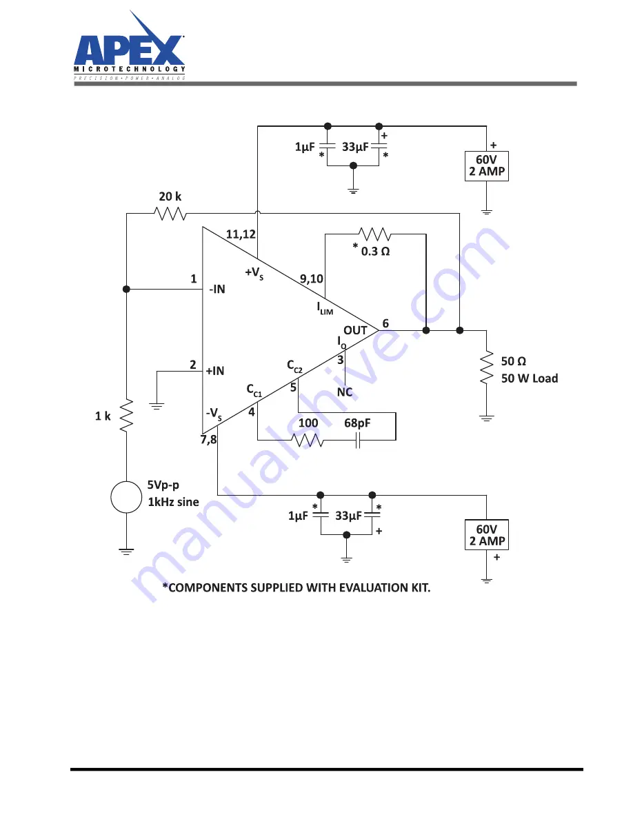
Figure 3: Test Circuit
Figure 3 shows a suggested simple test circuit that you can build to gain a familiarity with the evaluation
kit as well as the amplifier. At the output (pin 6) you should observe a 100 V p-p sine wave.
Page 1: ...tical connections for power supply bypassing com pensation and current limiting are pre wired Components not usually readily available in engineering labs are provided External connections to the eval...
Page 2: ...K Schematic Figure 2 shows the schematic of the evaluation kit s pre wired connections Components supplied with the kit are marked with an asterisk All other connections are made via the bread boardin...
Page 3: ...Figure 3 Test Circuit Figure 3 shows a suggested simple test circuit that you can build to gain a familiarity with the evaluation kit as well as the amplifier At the output pin 6 you should observe a...
Page 4: ...ircuit you will probably want to use the mating socket strip Clip off the strip after the 12th position Insert the strip into the circuit board from the DUT side and solder one pin on the reverse side...
Page 5: ...copyrights trademarks trade secrets or other intellectual property rights Apex Microtechnology owns the copyrights associated with the information contained herein and gives consent for copies to be m...