background image

June 2013 

16 

80-0180-347 Rev. A 

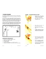
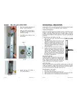
STEP 7     Mounting the A100-3090


 

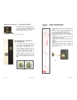
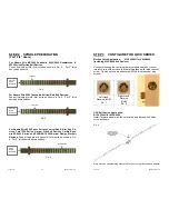
Insert  the  properly  dimensioned 
spindle into the output hub. 


 

Mount the A100 onto the mount-
ing bracket and guide the spindle 
into the Cam Plug. 


 

The  A100  must  sit  flush  on  the 
door surface. 


 

Secure  with  two  (2)  #10-32  x 
5/8” screws as shown.  


F

IG

. 20 

F

IG

. 19 

F

IG

. 21 

S

PINDLE


June 2013 

80-0180-347 Rev. A 

OPERATIONAL DESCRIPTION 


When the eForce

®

 is in a secured state, the LED in the front plastic faceplate 

will be off, and the lever will not operate the locking mechanism.  

Credential Card Operation 

When a user presents a supported credential to the lock, the Aperio system is 
designed  to  send  the  credential  wirelessly  to  the  Aperio  Hub.    The  Aperio 
Hub then communicates with an EAC system.  The EAC system provides the 
access decision to the Aperio Hub where access to the lock is either granted 
or denied. 

To gain entry using an iCLASS or Prox Card: 

 

Place card in front of the small plastic cover, at a 

distance  no  greater 

than one inch

.   

 

The  access  control  system  will  receive  the  card 
credential  information,  and  will  send  an  unlock 
signal to the eForce

® 

if the credentials are valid. 

 

The LED will change states from off to green, and 
a  short  audible  tone  will  be  heard  to  indicate  a 
valid unlock status. 

 

Rotate the lever to gain entry into the building. 

 

Deadlatch versions will return to a secured locked 
state  after  the  access  control  system  unlock  pe-
riod  has  expired.    Deadbolt  versions  will  remain 
unlocked  until  the  deadbolt  is  thrown  again.  
NOTE:  the  access  control  system  will  determine 
the  unlock  period.  There  are  no  adjustments  in 
the eForce

®

 for unlock period. 

Adding Card Credentials 
Consult the access control system manual or the sys-
tem  administrator  to  manage  your  credential  data-
base.  The eForce

®

 does not store card credentials; it 

simply  extracts  the  information  from  the  card  and 
sends it to the access control system for verification. 

Lock & Hub Pairing 
The  eForce  A100-3090H  is  paired  with  the  communication  hub  that  is  in-
cluded in the same box.  Locks and hubs cannot be interchanged in the field.  
If either the eForce A100-3090H or the communication hub require replace-
ment, both parts will need to be replaced at the same time. 

Manual Operation – Key Cylinder 
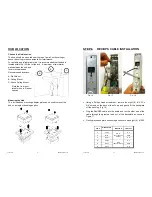
1.  Insert key into lock cylinder. 
2.  Turn the key 180° to the detent position and hold. 
3.  Rotate the lever until latch or deadbolt clear the strike and open the door. 
4.  Return the key to the 12 o’clock position and remove the key. 

Summary of Contents for eForce A100 A100-3090H

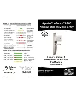
Page 1: ... S 51st St Suite 102 Phoenix AZ 85044 Phone 800 872 3267 Fax 800 232 7329 www adamsrite com NORMAL OPERATION LOCK INDICATIONS Aperio eForce A100 Narrow Stile Keyless Entry Adams Rite Manufacturing Co Phone 800 872 3267 www adamsrite com Owner s Manual Installation Instructions For Models A100 3090H ...

Page 2: ...n credential card in front of eForce If the eForce emits one short tone but lock does not activate check Wiegand data lines for connectivity and proper connec tion Green light comes on but lever will not retract latch or deadbolt Check the eForce body connection with lock latch mechanism Check the spindle length see installation instructions Check for proper door preparation refer to door template...

Page 3: ...evice pursuant to part 15 of the FCC Rules These limits are designed to provide reasonable protection against harmful interference in a residential installation This equipment generates uses and can radiate radio frequency energy and if not installed and used in accordance with the instructions may cause harmful interference to radio communications However there is no guarantee that interference w...

Page 4: ... Exit Devices Corbin Russwin ED4000 Series and SARGENT 8500 Narrow Design Rim Exit Devices OPERATIONAL SPECIFICATIONS IEEE 802 15 4 UHF Interface operating at 2 4GHz iCLASS or PROX Reader technology AES 128 bit encryption 4 AA battery operated Operating Temperature Range 31 to 150 F 35 to 65 C Operating Humidity Range 5 to 95 relative humidity non condensing June 2013 17 80 0180 347 Rev A STEP 8 B...

Page 5: ...are valid The LED will change states from off to green and a short audible tone will be heard to indicate a valid unlock status Rotate the lever to gain entry into the building Deadlatch versions will return to a secured locked state after the access control system unlock pe riod has expired Deadbolt versions will remain unlocked until the deadbolt is thrown again NOTE the access control system wi...

Page 6: ...the Hub The included hub mounting adapter plate can be used to mount the hub on a single or double gang box A B C June 2013 15 80 0180 347 Rev A STEP 6 REX DPS CABLE INSTALLATION PIN WIRE COLOR FUNCTION CONTACT 1 Yellow D P S Door Position Switch N C 2 Blue COM 3 Brown N O 4 Orange N C REX Request to Exit 5 White COM 6 Green N O Using a Phillips Head screwdriver remove the eight 8 10 32 x 5 8 scre...

Page 7: ...are wires connect ing the housing and back plate assembly Handle with care Do not over tighten Do not use Dummy Cylinder June 2013 7 80 0180 347 Rev A HUB WIRING The Aperio hub connects to the Access Control system via Wiegand wiring The hub requires 8 24VDC power 250mA The hub has four form C relays that can be used to transmit door position status re quest to exit low battery signal and a tamper...

Page 8: ...tem Description Qty 1 Mounting Bracket Part 22 9076 1 2 10 32 X 5 8 Phillips Pan Head Screws w Lockwasher 4 3 Spindle Part 22 9154 1 4 5 64 Allen Key 1 5 Cylinder Locking Ring Part 24 0061 1 6 Locking Ring Spanner Tool Part 22 0594 1 FIG 1 June 2013 13 80 0180 347 Rev A STEP 4 HANDING THE eForce The eForce is shipped in a non handed neutral position with the access cover off as shown To hand the e...

Page 9: ...screw and secure with the two 2 brass cam plug screws Cam Plug must be positioned below door sur face CYLINDER ACTUATOR SCREW FIG 11 FIG 10 FIG 12 June 2013 9 80 0180 347 Rev A STEP 1 DOOR PREPARATION FIG 2 Select the stick on template to match the appli cation For Yale Corbin Russwin and SARGENT exit devices use template 80 0180 396 01 Mark the backset and horizontal centerlines Apply clear templ...

Page 10: ... FIG 6 For 2 thick doors add two notches FIG 6 Insert T end into exit devices Fourteenth notch FIG 5 Sixth notch Insert Flat end into exit devices FIG 4 Fifth notch Insert Flat end into exit devices June 2013 11 80 0180 347 Rev A STEP 3 CONFIGURE FOR LOCK SERIES Mortise Latch Application A100 3090H for 4500 4900 including 8300 8400 Exit Devices Configure the supplied cam plug to match the hand of ...

Reviews: