Page 15
GENERAL
INFORMA
TION
AM
ER
IC
AN
P
ILE
DRIVING E
QU
IP
M
EN
T
J&
M
F
O
UN
DAT
ION EQ
UIP
M
EN
T
MODEL 10-4 HIH
Copyright © 2022 American Piledriving Equipment Inc. All Rights Reserved
800-248-8498
800-248-8498
WWW.AMERICANPILEDRIVING.
WWW.AMERICANPILEDRIVING.
com
com
EMERGENCY STOP:
WILL SHUT OFF
ENGINE, DISENGAGE
DRIVE AND ALL
VALVES INSTANTLY
.
Control panel will stay on.
ATTENTION:
POWER
E-STOP
Hammer Controls
Wired Pendant
IF EQUIPPED
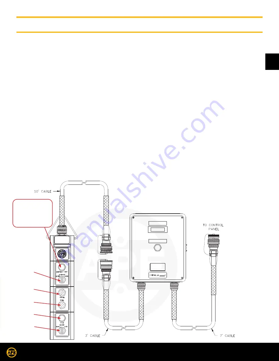
The hammer control consists of a Blow Count Box and a Pendant, connected via a multi conductor cable. The Blow Count Box should
be mounted to the Power Unit just below the Control Panel. The Blow count box is connected to the Control Panel via an Amphenol
Plug.
1. Emergency Stop Button:
The Emergency stop Button is located at the very top of the pendant station. Depressing this button will kill
the Power Unit Engine.
2. Governor Switch:
Turn this switch to the left “Lower” Engine RPM. Turn the switch to the right “Raise” Engine RPM.
Note:
If the engine rpm is increased while the hammer is operating, the stroke will increase.
3. Stroke Switch:
This switch is the primary control, regulating the time of the ram stroke. Turning the switch all the way to the “Left”
(approx 7 o’clock) will produce the shortest stroke. Turning the switch all the way to the “Right” (approx 5 o’clock) will produce
the longest stroke. Until the operator is really familiar with the hammer’s operational characteristics, the hammer should be started with
a short stroke setting, then increased after the hammer is operating.
Note:
If the engine rpm is increased while the hammer is operating, the stroke will increase.
Note:
The setting for a 4 ft drop, should be about .55 seconds.
4. Dwell Timer Switch:
It’s function is to regulate dwell time between ram impact and the beginning of the next lift cycle. Turning the
switch all the way to the “Left” (approx 7 o’clock) will produce the shortest dwell. Turning the switch all the way to the “Right”
(approx 5 o’clock) will produce the longest dwell. Until the operator is really familiar with the hammer’s operational characteristics, the
hammer should be started with a long Dwell setting, then decreased after the hammer is operating.
Note:
Allow enough time for the ram to come to rest before the lifting cycle starts again. When the dwell time is too short the ram
can be “caught” creating far to much hydraulic pressure in the cylinder. We never want to “catch” the falling ram.
5. Hammer Switch:
Turning this switch to “Hand” for intermittent stroke control. Turning this switch to the “Auto” will allow continuous use.
Note:
The engine can not be started if this switch in either Hand or Auto position. it must be in the middle “OFF” position.
6.
Cycle button:
With Hammer switch in
Hand
position pushing and holding the cycle button will raise the ram until the button is
released. When this button is released the ram will immediately fall. With the Hammer switch in the Auto position pushing the cycle
button will start and allow the hammer to run continuously. To stop the hammer turn the hammer switch to “OFF”.
The Emergency stop
Button is located at the
very top of the pendant
station. Depressing this
button will kill the Power
Unit Engine.
OPERATION / MAINTENANCE MANUAL
DASH 4 HYDRAULIC IMPACT HAMMER
7032 SOUTH 196th - KENT, WA 98032 - (800) 248-8498 / FAX (253) 872-8710
Page 4-1
Figure 4-A Blow Count Box and Pendant
Generation
Next
PLC HAMMER
RESET
BLOW COUNT
Generation
Next
IV. COMPONENT DEFINITION
IV-1. Blow Count and Pendant Layout
Governor
Stroke
Dewell
Cycle
Hand/Auto


