


EN
22 Symbol of annual data, indicating the display of
data from the annual archive.
23 Symbol of hourly data, indicating the display of ar-
chived data from the hourly archive.
24 Symbol of minute-based data, indicating the display
of data from the minute-based/configurable archive.
25 Symbol of tariff data, indicating the display of data
from the tariff archive.
26 Decimal symbol, indicating the decimal part of a
value or separating different values.
27 Decimal separator symbol, highlighting the decimal
part of a value.
28 Symbol of impulse frequency, indicating the im-
pulse frequency unit.
29 Unit field, indicating the unit of value displayed in
the main field, available units of energy, volume,
flow, power and time.
30. Register type symbol. Displayed only when the cal-
culator is configured to operate in the leak detection
system, only for the values determined for both sen-
sors (volume, weight, flow and error code). It speci-
fies the flow sensor which the displayed data relates
to: A - main flow sensor, B - additional sensor.
Error code description
Code
Description
Time
1
Long-time leak
conf.
2
No flow,
Δ
T difference correct
conf.
4
Error: supply temp. sensor
< 10 s
8
Error: return temp. sensor
< 10 s
16
Error: reverse temperature
difference
< 10 s
32
Error: (maximum) flow exceeded
< 10 s
64
Low main battery or no mains
power
< 10 s /
< 24 h
128
Low backup battery
< 24 h
256
Additional input alarm
< 1 s
512
Wrong flow direction
< 3 min.
1024 Air in flow meter
< 3 min.
2048 Flow meter’s measuring system
damaged
< 3 min.
4096 Error: no communication with flow
sensor
< 3 min.
8192 “Short-time” leak
conf.
16384 Improper module 1
< 10 s
32768 Improper module 2
< 10 s
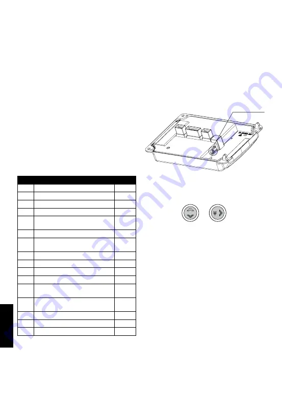
Configuration of the calculator from
the menu
The calculator allows for a manual configuration of
selected parameters from the menu. You can set
parameters such as date, time, network settings and
additional input settings. Configuration possibility is
secured by a configuration jumper available after open-
ing the casing (Fig. 35).
Upon pressing and holding the jumper for 1 second, the
configuration group selection screen is automatically
displayed (06). Configuration group is available for 5
minutes after using the jumper or after recent activity in
this group. After this time, the display automatically re-
turns from the configuration group to the main energy;
to enable configuration group, use the jumper again.
When the possibility of configuration is active, at any
time it is possible to exit and re-enter the group in a
standard way. Upon moving to the configuration menu
the current calculator configuration is read and then
displayed during editing.
Fig. 35.
Configuration jumper
Navigating between screens of the configuration group
takes place in a standard way.
Fig. 36.
P1
P2
Numeric value editing
To start editing a numeric value, briefly push the P2 but-
ton at the time of its display (Fig. 36). The first digit of the
edited value will start flashing. By briefly pushing the P2
button, set the appropriate value; to move to the next
digit editing, briefly push the P1 button (Fig. 36). To exit
the editing mode of a given value, go to the last editable
digit and briefly push the P1 button once more. As a
result, the last digit will stop flashing and the screen will
return to the value display mode, after which it will be
possible to select the next value to edit.
In this way it is possible to configure the following pa-
rameters in the calculator:
– date and time,
– network address and customer ID,
– impulse frequency and serial number for additional
inputs
– initial value of the meter for additional inputs.
Date and time editing
Configuration of date and time takes place on the same
menu screen. To edit the date, briefly push the P2 but-
ton when in the settings menu. Editing begins with
the year, each next push of the P1 button enables the
editing of the month, day, hour and minutes. Set date


