APAR - Sales Office
05-090 Raszyn, ul. Gałczyńskiego 6
Tel. (+48) 22-101-27-31, 22-853-48-56, 22-853-49-30
fax (+48) 22-101-27-33
Internet:
www.apar.pl
, email:
[email protected]
USER INSTRUCTION
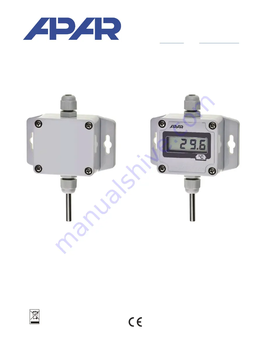
version version
without a display with an LCD display
TEMPERATURE TRANSDUCER
AR553
Version 3.0.0
2017.04.28


