


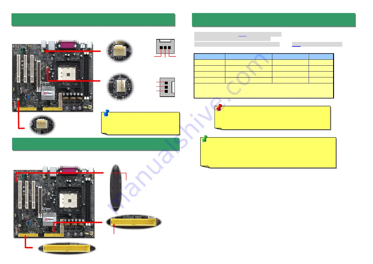
Plug in the CPU fan cable to the 3-pin
CPUFAN
connector. If you have chassis fan, you can
also plug it on
SYSFAN1
or
SYSFAN2
connector.
5. Setting CPU Voltage & Frequency
4. Connecting IDE & Floppy Connectors
3. Installing CPU & Housing Fan
Note: Some CPU fans do not have
sensor pin, so that they cannot
support fan monitoring.
SYSFAN1 Connector
CPUFAN Connector
Supported CPU Frequency
Core Frequency = CPU
Bus
Clock * CPU Ratio
Bus Speed = CPU external bus clock x 2
PCI Clock = CPU Bus Clock / Clock Ratio
AGP
Clock = PCI Clock x 2
CPU
CPU Core Frequency
Clock
Ratio
Athlon 64 3200+
1.8GHz
200MHz
9x
Athlon 64 3400+
2.0GHz
200MHz
10x
Athlon 64 3700+
2.2GHz
200MHz
11x
Athlon 64 4000+
2.4GHz
200MHz
12x
Note: With CPU speed changing rapidly, there might be faster CPU on the market by
the time you received this installation guide. This table is kindly for your references
only.
Tip: If your system hangs or fails to boot because of overclocking, simply use
<Home> key to restore the default setting or you can wait the AOpen “Watch
Dog ABS” reset the system in five seconds and system will auto-detect
hardware again.
Warning: nForce3 chipset supports 200MHz system clock and
66MHz AGP clock; higher clock setting may cause serious
system damage.
SYSFAN2 Connector
GND
+12V
SENSOR
Connect 34-pin floppy cable and 40-pin IDE cable to floppy connector FDD connector. Be
careful of the pin1 orientation. Wrong orientation may cause system damage.
Pin 1
FDD Connector
IDE 2 (Secondary)
IDE 1(Primary)
Pin 1
GND
SENSOR
+12V


