93
A
X
4
5
F
-
8
M
a
x
O
n
l
i
e
u
11. Confirming Windows 98 Installation
Page 1: ...1 A AX X4 45 5F F 8 8X X M Ma ax x O On nl li in ne e M Ma an nu ua al l AX45F 8X Max DOC NO AX45F8XMAX OL E0307A...
Page 2: ...w 10 Feature Highlight 11 Quick Installation Procedure 15 Motherboard Map 16 Block Diagram 17 Hardware Installation 18 About User Upgrade Optional and Manufacture Upgrade Optional 19 EzColor 20 CPU In...
Page 3: ...Connector 45 Support AGP 8X Accelerated Graphic Port Expansion Slot 46 AGP Protection Technology and AGP LED 47 Wake On Modem Wake On LAN Wake On PCI Card 48 Support Gigabit LAN Chip onboard 49 Suppor...
Page 4: ...Dr Voice II Language Select Jumpers 64 JP24 JP25 BIOS Rescue Jumper 65 JP28 Keyboard Mouse Wake up Jumper 66 STBY LED 67 Enlarged Aluminum Heatsink 68 Resetable Fuse 69 3300 F Low ESR Capacitor 70 EzC...
Page 5: ...XP 90 Installing Serial ATA Driver in Win98SE ME NT4 0 2000 XP 107 Installing USB 2 0 Driver 119 Glossary 120 AC97 CODEC 120 ACPI Advanced Configuration Power Interface 120 ACR Advanced Communication...
Page 6: ...Pin Grid Array 124 FC PGA2 Flip Chip Pin Grid Array 124 Flash ROM 125 Hyper Threading 125 IEEE 1394 125 Parity Bit 126 PCI Peripheral Component Interface Bus 126 PDF Format 126 PnP Plug and Play 126 P...
Page 7: ...n ne e M Ma an nu ua al l SPD Serial Presence Detect 128 USB 2 0 Universal Serial Bus 128 VCM Virtual Channel Memory 129 Wireless LAN 802 11b 129 ZIP file 129 Troubleshooting 130 Technical Support 134...
Page 8: ...on this manual are used for identification purposes only and may be the registered trademarks of their respective owners All of the specifications and information contained in this manual are subject...
Page 9: ...ystem configuration changes This Online Manual is saved in PDF format we recommend using Adobe Acrobat Reader 5 0 for online viewing it is included in Bonus CD or you can get free download from Adobe...
Page 10: ...fferent customer s requirements AX45F 8X Max supports DDR 400 333 266 RAM up to 3GB maximum The onboard IDE controller supports Ultra DMA 66 100 133 mode and Serial ATA 150 MB s There are 6 PCI slots...
Page 11: ...ntegrates a high performance host interface for Intel Pentium 4 processor a high performance memory controller an AGP interface and SiS MuTIOL 1G Technology connecting with SiS963L MuTIOL 1G Media IO...
Page 12: ...cy Adjustment function in the BIOS This magic function allows you to adjust CPU FSB 1GB RAM up to 3 GB maximum Hyper Threading Technology Support Hyper Thread can be managed Watch Dog ABS Includes AOp...
Page 13: ...orts Enhanced IDE devices Sound On board AC 97 AX45F 8X Max uses RealTek ALC650 AC97 sound chip This on board audio includes a complete audio recording and playback system Six USB 2 0 Ports Provides f...
Page 14: ...tion Agency The Dr Voice II can identify what kind of pro l German four kinds language versions S PDIF Sony Philips Digital Inte and allows you to enjoy digital audio instead of analog audio On boa Co...
Page 15: ...st ta al ll la at ti io on n P P age gives you a quick procedure on how Inst and Fan 2 Installing System Memory DIMM 3 Connecting Front Panel Cable Connecting IDE and Floppy Cable 4 Connecting ATX Po...
Page 16: ...martEAR Connector ports DDR maximum up to 3GB r ATX Power Connecto rature SIS 648FX 963 Chipset 478 pin CPU socket with Voltage and Frequency Auto detection that supports Intel entium 4 1 6 3 20GHz CP...
Page 17: ...rt USB2 0 Ports x6 32 bit PCI Slot x6 Parallel Port IDE Drive x6 ATA 66 100 133 DDR400 333 266 RAM Up to 3GB Primary Channel Secondary Channel 2Mbit Flash EEPROM PCI Bus ITE IT8705F Floppy Disk Drive...
Page 18: ...your processor disk drives expansion boards and other components Always observe the following precautions before you install a system component 1 Do not remove a component from its protective packagin...
Page 19: ...l Although all of AOpen s motherboards have included many amazing and powerful features sometimes not every user is familiar with these powerful features As a result of this we define features that ca...
Page 20: ...c connector and module components on motherboard are now born with their respective colors Users may now easily recognize what jumper or cable should match with specific jumper or cable by COLOR witho...
Page 21: ...al l Claret Serial ATA connector 1 IDE LED SPEAKER Power Switch ACPI Power LED Navy Blue IDE 1 Connector RESET Black IDE 2 Connector Light Yellow IDE 3 Connector Note Colors setting varies on differe...
Page 22: ...l Pentium 4 Socket 478 series CPU Northwood Be careful of CPU orientation when you plug it into CPU socket 2 Locate Pin 1 in the socket and look for mark on the CPU upper interface Match Pin 1 and cut...
Page 23: ...ll you may damage the CPU 3 Press down the CPU socket lever and finish CPU CPU cut edge Note This socket supports Micro FC PGA2 package CPU which is the latest CPU package developed by Intel Other for...
Page 24: ...strongly recommend you to install Open speci signed CPU Fan as shown below on module for better heat dissipation Please install the CPU Fan orrectly as the f ing pictures shown 1 ached on the on the...
Page 25: ...l state The right hand configuration represents an Intel Hyper Threading technology based processor You can see that the architectural state for each processor is duplicated while the execution resour...
Page 26: ...xecution resources the second thread can use resources that would be otherwise idle if only one thread was executing This results in an increased utilization of the execution resources within each phy...
Page 27: ...ction and allows the user to set the CPU frequency through the BIOS setup therefore no jumpers or switches are used The disadvantages of the Pentium based jumper less designs are eliminated There will...
Page 28: ...ard supporting CPU over current protection in conjunction with 3 3V 5V 12V power supply provide the full line over current protection Note Although we have implemented protection circuit try to preven...
Page 29: ...ency according to user s settings stored in the BIOS If system failed in BIOS POST the Watch Dog Timer will reset the system to reboot in five seconds Then BIOS will detect the CPU s default frequency...
Page 30: ...OS Setup configurations The RTC real time clock can also keep running as long as the power cord is plugged If you lose your CMOS data by accident you can just reload the CMOS configurations from Flash...
Page 31: ...Core Voltage S Se et tt ti in ng g C CP PU U F Fr re eq qu ue en nc cy y BIOS Setup Frequency Voltage Control CPU Bus Frequency This motherboard is CPU jumper less design you can set CPU frequency thr...
Page 32: ...2800MHz 200MHz 800MHz 14x Pentium 4 3 00G 3000MHz 200MHz 800MHz 15x Pentium 4 3 06G 3060MHz 133MHz 533MHz 23x Pentium 4 3 20G 3200MHz 200MHz 800MHz 16x Warning SIS 648FX chipset supports maximum 400M...
Page 33: ...n white in EzColor Please plug in the CPU fan cable to the 3 pin CPUFAN1 connector If you have chassis fan you can also plug it on SYSFAN2 or SYSFAN3 connector The PowerFAN4 is for SilentTek II functi...
Page 34: ...The DIMM sockets are painted in electric blue and only support non ECC DDR RAM Please install the suitable RAM modules otherwise serious damage may occur on memory sockets or you RAM modules Please n...
Page 35: ...h the socket s size as depicted below 2 Insert the module straight down to the DIMM slot with both hands and press down firmly until the DIMM module is securely in place Note The tabs of the DIMM slot...
Page 36: ...IOS Setup the ACPI Power LED will keep flashing or high light while the system is in suspend mode Locate the power switch cable from your ATX housing It is 2 pin female connector from the housing fron...
Page 37: ...connect the 4 pin 12V ATX connector before connecting the 20 pin ATX power connector and use standard power supply specially designed for Pentium 4 system A AC C P Po ow we er r A Au ut to o R Re ec c...
Page 38: ...ble and 40 pin IDE cable to floppy connector FDD and IDE connector The IDE 1 connector is painted in navy blue the IDE 3 connector is painted in light yellow the IDE 2 connector and FDD connector are...
Page 39: ...setting as master or slave mode depends on the jumper on your IDE device so please refer to your hard disk and CDROM manual accordingly Warning The specification of the IDE cable is a maximum of 46cm...
Page 40: ...ng systems such as Window XP that demand more storage space and faster data transfer rates from more responsive computing experiences To make good use of this new technology and enjoy its best perform...
Page 41: ...an illustrious track record the specification is now showing its age and imposes some serious design issues on today s developers including a 5 volt signaling requirement high pin count and serious ca...
Page 42: ...lease be noted that it is a jumper free implement you don t need to set jumpers to define a master or slave disk When serial ATA hard disks are installed on serial ATA ports the one connected on Port...
Page 43: ...installed Serial ATA hard disks on your operating system after you have had installed them on the problem mainly lies in the BIOS setting You may simply adjust BIOS settings to have them work properly...
Page 44: ...etect all hard disks 3 Combined Mode If you have had installed traditional IDE hard disks and Serial ATA hard disks at the same time then you may choose this Combined Mode Under this mode you may rand...
Page 45: ...as Laplink or Windows 98 Direct Cable Connection the user can transfer files to or from laptops notebooks PDA devices and printers This connector supports HPSIR 115 2Kbps 2 meters and ASK IR 56Kbps In...
Page 46: ...provement on the performance of 3D graphic AGP supports only memory read write operation and single master single slave one to one only AGP uses both rising and falling edge of the 66MHz clock for 2X...
Page 47: ...ection Technology is implemented this motherboard will automatically detect the voltage of AGP card and prevent your chipsets from being burnt out Please note that if you install a AGP card with 3 3V...
Page 48: ...cial circuit to support Wake On Modem Wake On LAN and Wake On PCI Card Green PC suspend mode does not really turn off the system power supply it can be triggered by Modem LAN or Other PCI Cards and re...
Page 49: ...on top of USB connectors The right hand side LED indicates the link mode it blinks in orange whenever linking to network The left hand side LED indicates the Connecting mode and it lights in green whe...
Page 50: ...o connect USB devices from back panel or connect USB 2 0 header to the front panel of chassis Compared to traditional USB 1 0 1 1 with the speed of 12Mbps USB 2 0 has a fancy speed up to 480 Mbps whic...
Page 51: ...s 12Mbps Hence the IEEE 1394 interface can connect with the devices that need high data transferring performance such as digital camera scanner or others IEEE 1394 devices Please use the proper cable...
Page 52: ...INE IN USB Ports SPEAKER OUT MIC IN PS 2 Keyboar For standard keyboard which use d PS 2 plug others serial devices ector ut er Earphone or Amplifier Line In Comes from the signal sources such as CD Ta...
Page 53: ...Normally there are two S PDIF outputs as shown one for RCA connector the most common one used for consumer audio products and the other for optical connector with a even better audio quality Through a...
Page 54: ...ign of ALC650 you re able to use standard line jacks for surround audio output without connecting any external module To apply this function you have to install the audio driver in the Bonus Pack CD a...
Page 55: ...el through this connector By the way please remove the jumper cap from the Front Audio Connector before you connect the cable Do not remove this yellow jumper cap if your housing doesn t have an audio...
Page 56: ...o on na al l Connecting Dr LED you can easily the 8 LED lig find the system problems that may occur while assembling It can clearly indicate whether the roblem components or improper installation thro...
Page 57: ...7 6 5 4 3 2 1 0 Boot O K KB H The total 8 LEDs light up alternatively if the system fails in one of eight stages Once system has completed its boot up procedure The 8 LEDs indicate the following messa...
Page 58: ...only applies to advanced chassis this function The CASE OPEN header provides chassis intrusion monitoring function To make this f system BIOS connect this header to a sensor somewhere on the chassis S...
Page 59: ...M Ma ax x 59 O On nl li in ne e M Ma an nu ua al l CD IN Connector ND L C CD D A Au ud di io o C Co on nn ne ec ct to or r This connector is used to connect CD Audio cable from CDROM or DVD drive to...
Page 60: ...8 8X X M Ma ax x O On nl li in ne e M Ma an nu ua al l A AU UX X I IN N C Co on nn ne ec ct to or r This GREEN connector is used to connect MPEG Audio cable from MPEG card to onboard sound R GND GN L...
Page 61: ...ard comes with a game port Joystick Midi for you to connect any midi devices or joysticks To use this function you have to have a joystick module and connect it with a game port cable to this port on...
Page 62: ...r This motherboard comes with another considerate option that allows you to turn off the voice from buzzer and speaker You can choose not to be bothered by the warning made from Dr Voice II when it d...
Page 63: ...procedure below 1 Turn off the system and unplug the AC power 2 Remove ATX power cable from connector PWR2 3 Locate JP14 and short pins 2 3 for a few seconds 4 Return JP14 to its normal setting by sh...
Page 64: ...is a great feature which can identify the problems you may encounter in the operating system It can clearly tell you whether the problem is caused from components or improper installation such as CPU...
Page 65: ...th EZWinflash For Flashing BIOS under DOS system please unzip the BIOS version after downloading from website and execute it under DOS These two versions of BIOS have been provided on our website for...
Page 66: ...r r This motherboard provides PS2 keyboard mouse wake up function You can use JP28 to enable or disable this function which could resume your system from suspend mode with keyboard or mouse The factor...
Page 67: ...to the motherboard This is a convenient indication for er on off stand by mode and RAM power status during stem information The STBY LED will light up when ower is provide you to check the system pow...
Page 68: ...nu ua al l E En nl la ar rg ge ed d A Al lu um mi in nu um m H He ea at ts si in nk k Cool down CPU and Chipset are important for system reliability Enlarged aluminum heat sink provides better heat co...
Page 69: ...ent Keyboard and USB port from over current or shortage These fuses are soldered onboard that when it is broken function to protect motherboard user cannot replace them and result in malfunction of mo...
Page 70: ...quivalen Series Resistance during high frequency operation is very important for the stability of CPU power The idea of where t to put these capacitors is another know how that requires experience and...
Page 71: ...hen overclocking A typical CPU core voltage is 2 0V so a good design should control voltage between 1 860V and 2 140V That is the transient must be below 280mV Below is a timing diagram captured by a...
Page 72: ...S screen for the frequency and reboot the system again and again But from now on you don t surfer the boring stuffs anymore With brand new and user friendly EzClock that AOpen specially designs for hi...
Page 73: ...nd turns red After finishing those value settings you can press Apply button on the upper right hand corner to save changes to CMOS VGA AGP PCI and DRAM Voltage Clock Area Pressing _ and buttons you c...
Page 74: ...age and CPU temperature in Celsius and Fahrenheit degrees How You Adjust the Settings in BIOS Apart from EzClock utility the voltage and frequency values of CPU PCI and memory can also be adjusted on...
Page 75: ...the shown picture here Every time you boot your system both default and current settings will pop up on the screen Your personal settings that had been adjusted earlier will be highlighted thus you c...
Page 76: ...such as motherboard CPU memory PCI devices and IDE devices The powerful utility also displays the version of BIOS and firmware for your convenience of maintenance Moreover AOConfig allows users to sav...
Page 77: ...and capacity 4 From this page users can r detailed information could be saved in bmp or txt format obtain the technical support information of AOpen Moreove NO operated in a system equipped with an AO...
Page 78: ...ides critical low level support for standard devices such as hard disk drives serial and parallel ports Most BIOS settings of this model have been optimized by AOpen s R D engineering team But the def...
Page 79: ...etailed description further powerful functions and advanced setting of BIOS Key Description Page Up or Changing setting to next value or increase the value Page Down or Changing setting to previous va...
Page 80: ...ne e M Ma an nu ua al l Self Test and choose Load Setup Defaults for recommended optimal performance Del Warning Please avoid of using Load Turbo Defaults unless you are sure your system components C...
Page 81: ...r system from any possible failure Moreover EzWinFlash has been taken into consideration to go with any windows platform you might be using no matter if you re using Windows 95 98 98SE ME NT4 0 2000 o...
Page 82: ...ck 7 Press Del at POST to enter BIOS setup choose Load Setup Defaults then Save Exit Setup Done 3 Save the unzipped files into a folder for example WAX45F8XMAX102 EXE WAX45F8XMAX102 BIN Double click o...
Page 83: ...vely designed with multi language support There are various widely use languages provided on our website for your downloading which also helps to prevent wrong settings caused by misunderstanding of t...
Page 84: ...setup default setting F7 Load turbo setting F10 Save changed setting and exit setup program F12 Full Screen Normal Mode Caution After updating your BIOS please remember to update WinBIOS profile as we...
Page 85: ...design VividBIOS now brings you a beautiful and sleek 256 colors screen without missing any important information shown on POST screen In addition the limited space of BIOS ROM is another big issue W...
Page 86: ...ll of them to boot your system But after you finish the hardware installation you have to install your operation system first such as Windows XP before you install any drivers or utilities Please refe...
Page 87: ...87 A AX X4 45 5F F 8 8X X M Ma ax x O On nl li in ne e M Ma an nu ua al l I In ns st ta al ll li in ng g A AG GP P D Dr ri iv ve er r You can find AGP driver from the Bonus Pack CD auto run menu...
Page 88: ...I In ns st ta al ll li in ng g O On nb bo oa ar rd d S So ou un nd d D Dr ri iv ve er r T ith RealTek ALC650 AC97 CODEC This audio driver supports Windows 98SE and uppe e Bonus Pack CD auto run menu h...
Page 89: ...9 A AX X4 45 5F F 8 8X X M Ma ax x O On nl li in ne e M Ma an nu ua al l I In ns st ta al ll li in ng g I ID DE E D Dr ri iv ve er r To use IDE devices you have to install IDE driver from Bonus Pack C...
Page 90: ...D Dr ri iv ve er r i in n W Wi in n9 98 8S SE E M ME E 2 20 00 00 0 X XP P Windows 98 SE Installation Guide 1 Open the Device Manager and check if there is a PCI Ethernet Controller in Other devices...
Page 91: ...er than the one your device is using now Recommended 6 Select Specify a location and type G Driver LAN RTL8100S 32 Win98 in the text box that appears Press Next 7 System will ask you to provide the fi...
Page 92: ...92 A AX X4 45 5F F 8 8X X M Ma ax x O On nl li in ne e M Ma an nu ua al l 8 System will ask you to insert Windows 98 CD ROM 9 Driver installed 10 Restart computer...
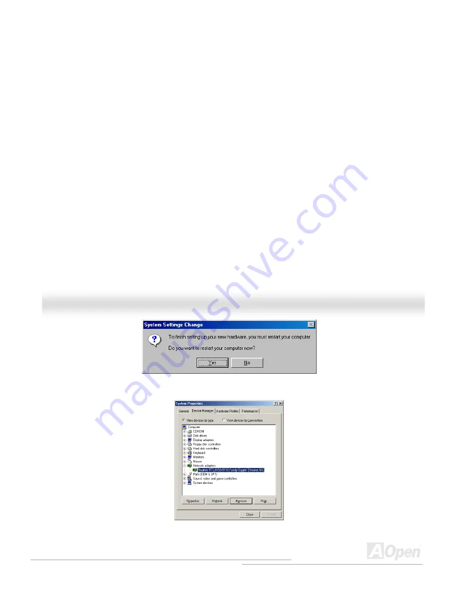
Page 93: ...93 A AX X4 45 5F F 8 8X X M Ma ax x O On nl li in ne e M Ma an nu ua al l 11 Confirming Windows 98 Installation...
Page 94: ...M Ma an nu ua al l Windows ME Installation Guide 1 Open the Device Manager and check if there is a PCI Ethernet Controller in Other devices 4 Click Reinstall Driver in the General Tab 2 Insert the su...
Page 95: ...l 5 Select Specify the location of the driver Advanced 6 Choose Search for a better driver than the one your device is using now Recommended then Select Specify a location and type G Driver LAN RTL81...
Page 96: ...96 A AX X4 45 5F F 8 8X X M Ma ax x O On nl li in ne e M Ma an nu ua al l 8 Restart computer 9 Confirming Windows ME Installation...
Page 97: ...an nu ua al l Windows NT 4 0 Installation Guide 1 In the Control Panel double click the Network icon When the Network window opens select the Adapters tab 2 Click Add to install a new adapt Network Ad...
Page 98: ...lect Network Adapter window opens click Have Disk 4 When prompted insert the BONUS CD type the path G Driver LAN RTL8100S 32 Winnt4 to the driver and click OK 5 With Realtek RTL8169 8110 Family Gigabi...
Page 99: ...99 A AX X4 45 5F F 8 8X X M Ma ax x O On nl li in ne e M Ma an nu ua al l 7 Confirming Windows NT Installation...
Page 100: ...l li in ne e M Ma an nu ua al l Windows 2000 Installation Guide 1 Open the Device Manager and check if there is a Ethernet Controller in Other devices 2 Insert the supplied Bonus CD 3 Right click Ethe...
Page 101: ...101 A AX X4 45 5F F 8 8X X M Ma ax x O On nl li in ne e M Ma an nu ua al l 4 Click Reinstall Driver in the General Tab 5 Select Search for a suitable driver for my device recommended...
Page 102: ...102 A AX X4 45 5F F 8 8X X M Ma ax x O On nl li in ne e M Ma an nu ua al l 6 Select Specify a location and then click Next 7 in the text box that appears Press OK Type G Driver LAN RTL8100S 32 Win2000...
Page 103: ...103 A AX X4 45 5F F 8 8X X M Ma ax x O On nl li in ne e M Ma an nu ua al l 8 er installed Driv Confirming Windows 2000 Installation 9...
Page 104: ...li in ne e M Ma an nu ua al l Installation Guide e Device Manager and check if there is a Ethernet Controller in Windows XP 1 Open th Other devices 2 Insert the supplied Bonus CD 3 Right click Ethern...
Page 105: ...al l 4 Select Install from a list or specific location Advanced and then click Next 5 locations and then r LAN RTL8100S 32 WinXP Choose Search for the best driver in these select Include this locatio...
Page 106: ...106 A AX X4 45 5F F 8 8X X M Ma ax x O On nl li in ne e M Ma an nu ua al l 6 installed Driver Confirming Windows XP Installation 7...
Page 107: ...Mass Storage Controller Choose it and then press the 8 Choose Rein t Windows 98 SE Installation Guide Installing Drivers during Windows 98 SE Installation The following details the installation alread...
Page 108: ...ing steps 1 Choose Settings from the Start menu e click on the System icon 3 Choose the Device Manager tab and then click the in front of SCSI controllers Win98 ME Promise SATA150 TX2plus tm IDE rch f...
Page 109: ...the Serial ATA drivers while installing Windows ME with the Serial ATA controller is enab already 1 Install Windows Me fully 2 After installation go the Start menu and choose Settings 3 From the Setti...
Page 110: ...2 Press Next then Finish Confirming Driver Installation in Windows ME To confirm that the driver has been properly loaded in Windows ME perform the following steps 1 Choose Settings from the Start men...
Page 111: ...your computer s hardware configuration appears 2 When the Windows NT Setup window is generated press S to specify an Additional Device s 3 Use or to select Other and press the Enter key 4 Insert the d...
Page 112: ...rs with Existing Windows NT 4 0 If you wish to use your current bootable drive with the Windows NT4 operating system on the SATA150 perform the steps below while the boot drive is still att until the...
Page 113: ...ttes b Floppyless Install Boot from floppy and type WINNT After files have been copied the system will reboot On the reboot press F6 after the message Setup is inspecting your computer s hardware conf...
Page 114: ...in the text box that appears Press OK installation Installing Driver in Existing Windows 2000 System WARNING If you will be moving the boot drive containing the existing Windows 2000 operating system...
Page 115: ...2plus tm IDE Controller should 1 From Windows 2000 open the Control Panel from My Computer followed by the System icon 2 Choose the Hardware tab and then click the Device Manager tab 3 Click the in fr...
Page 116: ...F6 if you need to install third party SCSI or RAID driver appears 2 When the Windows XP Setup window is generated press S to Specify an Additional Device s 3 Insert the Promise SATA150 driver diskette...
Page 117: ...he SATA150 driver MUST be loaded on to this hard drive while it is still attached to your existing hard drive controller Do not ws XP Mass Storage Install from a list or special location Advanced The...
Page 118: ...e Hardware tab and then click the Device Manager tab 5 Click the in front of SCSI controllers Win XP Promise SATA TX2plus tm IDE Controller should appear omise SATA150 driver diskette i 4 Type A in th...
Page 119: ...X4 45 5F F 8 8X X M Ma ax x O On nl li in ne e M Ma an nu ua al l I In ns st ta al ll li in ng g U US SB B 2 2 0 0 D Dr ri iv ve er r In Bonus Pack CD you can install USB 2 0 driver from the followin...
Page 120: ...o other application process as well We called CODEC that meets this structure AC97 CODEC A AC CP PI I A Ad dv va an nc ce ed d C Co on nf fi ig gu ur ra at ti io on n P Po ow we er r I In nt te er rf...
Page 121: ...A Au ud di io o M Mo od de em m R Ri is se er r The CODEC circuit of AC97 sound modem solution can be put on motherboard or put on a riser card AMR card that connects to motherboard through AMR conne...
Page 122: ...rivers is required to access BIOS without directly access hardware devices B Bl lu ue et to oo ot th h Bluetooth is a wireless transferring technology that enables short range wireless connections bet...
Page 123: ...on FSB frequency DDR RAM on the market are DDR200 DDR266 and DDR333 with more coming around soon DDR200 transfer bandwidth up to 200x64 8 1600MB s PC1600 DDR266 transfer bandwidth up to 266x64 8 2100M...
Page 124: ...us Speed CPU external bus clock x 2 200 MHz EV6 bus 200MHz 100 MHz external bus clock x 2 F FC CC C D Do oC C D De ec cl la ar ra at ti io on n o of f C Co on nf fo or rm mi it ty y The DoC is compone...
Page 125: ...nd interconnection system The main feature of the Firewire that assures its adoption for the digital video and audio A V consumer application is its low cost Fire wire interface is capable of supporti...
Page 126: ...ts providing a 33 MHz clock speed with a throughput rate of 133 MBps P PD DF F F Fo or rm ma at t With PDF file it is easy to do universal document exchange Virtually any document may be converted in...
Page 127: ...e use of multiple channels in ture of Multibank which is quite different from FPM EDO SDRAM Using different transfer rate of 600 700 800MHz providing bandwidth as high to 1 6GB us s I In nl li in ne e...
Page 128: ...nsfer rate of SMBus is only 100Kbit s it allows one host to communicate with CPU and many masters and slaves to send receive message S SP PD D S Se er ri ia al l P Pr re es se en nc ce e D De et te ec...
Page 129: ...2 2 1 11 1b b 802 11 is a specification developed by IEEE and Wireless LAN technology which is an interface between a wireless client and a base station or between two wireless clients 802 11 families...
Page 130: ...u system follow the procedures accordingly to resolve the problem Turn off the power and unplug the AC power cable then remove all of the add on cards and cables including VGA IDE FDD COM1 COM2 and pr...
Page 131: ...e Install the VGA card Then connect your monitor and keyboard The problem is probably caused by power supply or motherboard failure Please contact your reseller or local distributor for repairing Turn...
Page 132: ...l Continue Yes It is very possible that your keyboard is defective No Check if the system reboots Yes Check if there is display Perhaps your VGA card or monitor is defective No Press Ctrl and Alt key...
Page 133: ...ing system rebooting press Del to enter BIOS setup Choose Load Setup Default Check if the system can reboot successfully No The problem should be caused by the IDE cable or HDD itself End Yes Turn off...
Page 134: ...d then select your preferred language Under Type directory choose Manuals to go to our manual database You can also find the manual and EIG in AOpen Bonus Pack http download aopen com tw downloads Tes...
Page 135: ...d language under Multi language http club aopen com tw forum 5 5 6 6 7 7 Contact Distributors Resellers We sell our products through resellers and integrators They should know your system configuratio...
Page 136: ...be er a an nd d S Se er ri ia al l N Nu um mb be er r r The Part Number and Serial number are printed on bar code label You can find this bar code label on the outside packing or on component side of...
Page 137: ...OS S v ve er rs si io on n Model name and BIOS version can be found on upper left corner of first boot screen POST screen For example AX45F 8X Max R1 00 Jul 1 2003 AOpen Inc Phoenix Award Plug and Pl...
Page 138: ...Its purpose is to alert consumers quickly and conveniently when products contain technical issues Receive email notification about latest product s announcements Be able to personalize your AOpen web...
Page 139: ...21 6225 7926 Tel 1 510 498 8928 Fax 1 408 922 2935 Web Site http www aopen com tw AOpen Computer b v Tel 31 73 645 9516 Email support aopen nl Germany AOpen Computer GmbH Tel 49 2131 1243 710 Fax 49...