


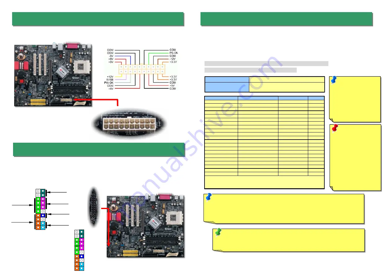
3. Connecting ATX Power Connector
5. Setting CPU Voltage & Frequency
The ATX power supply uses a 20-pin connector shown below. Make sure you plug in the
right direction.
Note:
Due to the limitation of nVidia chipset itself, if the FSB overclocking frequency is
extremely high, (for example, over 160MHz), the Watch Dog ABS and Home key
function may not be able to automatically recover your motherboard. In such case,
please clear CMOS by JP14.
Full-range Adjustable CPU Core Voltage
This motherboard supports CPU VID function. The CPU core voltage will be automatically
detected and the range is from 1.1V to 1.85V. It is not necessary to set CPU Core Voltage.
Setting CPU Frequency
This motherboard is CPU jumper-less design, you can set CPU frequency through the
BIOS setup, and no jumpers or switches are needed.
BIOS Setup > Frequency / Voltage Control > CPU Speed Setup
Core Frequency = CPU FSB Clock * CPU Ratio
CPU Ratio
From 5.5x to 16x step 0.5x
CPU FSB (Adjustment
manually)
FSB = 100MHz-200MHz by 1MHz Stepping
CPU Overclocking
CPU
CPU Core Frequency
EV6 Bus Clock
Ratio
Athlon 1G
1GHz
266MHz
7.5x
Athlon 1.13G
1.13GHz
266MHz
8.5x
Athlon 1.2G
1.2GHz
266MHz
9.0x
Athlon 1.33G
1.33GHz
266MHz
10.0x
Athlon 1.4G
1.4GHz
266MHz
10.5x
AthlonXP 1500+
1.3GHz
266MHz
10.0x
AthlonXP 1600+
1.4GHz
266MHz
10.5x
AthlonXP 1700+
1.46GHz
266MHz
11.0x
AthlonXP 1800+
1.53GHz
266MHz
11.5x
AthlonXP 1900+
1.6GHz
266MHz
12.0x
AthlonXP 2000+
1.667GHz
266MHz
12.5x
AthlonXP 2100+
1.73GHz
266MHz
13x
AthlonXP 2200+
1.80GHz
266MHz
13.5x
AthlonXP 2400+
2.0GHz
266MHz
15x
AthlonXP 2600+
2.13GHz
266MHz
16x
AthlonXP 2700+
2.16GHz
333MHz
13x
AthlonXP 2800+
2.25GHz
333MHz
13.5x
Duron 1G
1GHz
200MHz
10.0x
Duron 1.1G
1.1GHz
200MHz
11.0x
Duron 1.2G
1.2GHz
200MHz
12.0 x
Duron 1.3G
1.3GHz
200MHz
13.0 x
Note:
With CPU speed changing rapidly, there might be fastest CPU on the
market by the time you received this installation guide. This table is kindly for
your references only.
Note:
You have to
adjust CPU FSB in
BIOS after installing
CPU; otherwise CPU
will run at default
speed of CPU FSB
value.
Tip: If your system hangs or fails to boot because of overclocking, simply use
<Home> key to restore the default setting or you can wait the AOpen “Watch Dog
Timer” reset the system in five seconds and system will auto-detect hardware again.
Warning:
nForce2- GT
chipsets support
166MHz FSB (with
performance reaches
maximum 333MHz
EV6 system bus) and
66MHz AGP clock,
higher clock setting
may cause serious
system damage.
4. Connecting Front Panel Cable
Attach the power LED, speaker, and reset switch connectors to the corresponding pins. If
you enable “Suspend Mode” item in BIOS Setup, the ACPI & Power LED will keep flashing
while the system is in suspend mode.
Locate the power switch cable from your ATX housing. It is 2-pin female connector from the
housing front panel. Plug this connector to the soft-power switch connector marked
SPWR
.
1
Speaker
IDE LED
ACPI LED
(Blue)
Reset
NC
NC
+5V
IDE LED
IDE LED
+5V
+5V
GND
NC
SPEAKER
ACPI & PWR
LED
SPWR
1
SPWR
GND
ACPI LED-
GND
ACPILED
NC
ACPI_B
GND
RESET
GND


