background image


25


Picture-in-Picture 

You can select Picture-in-Picture (PIP) display mode to display 

two different pictures on the screen. 

Note: TV and audio pictures cannot be displayed at the same time 

under PIP mode.   

When the component input is YCBCR, if the primary 

picture input is TV or VIDEO, then only YCBCR and 

S-VIDEO can be displayed as the secondary picture.   

When the component input is YPBPR, if the primary 

picture input is TV or VIDEO, then only S-VIDEO can be 

displayed as the secondary picture. 

1.


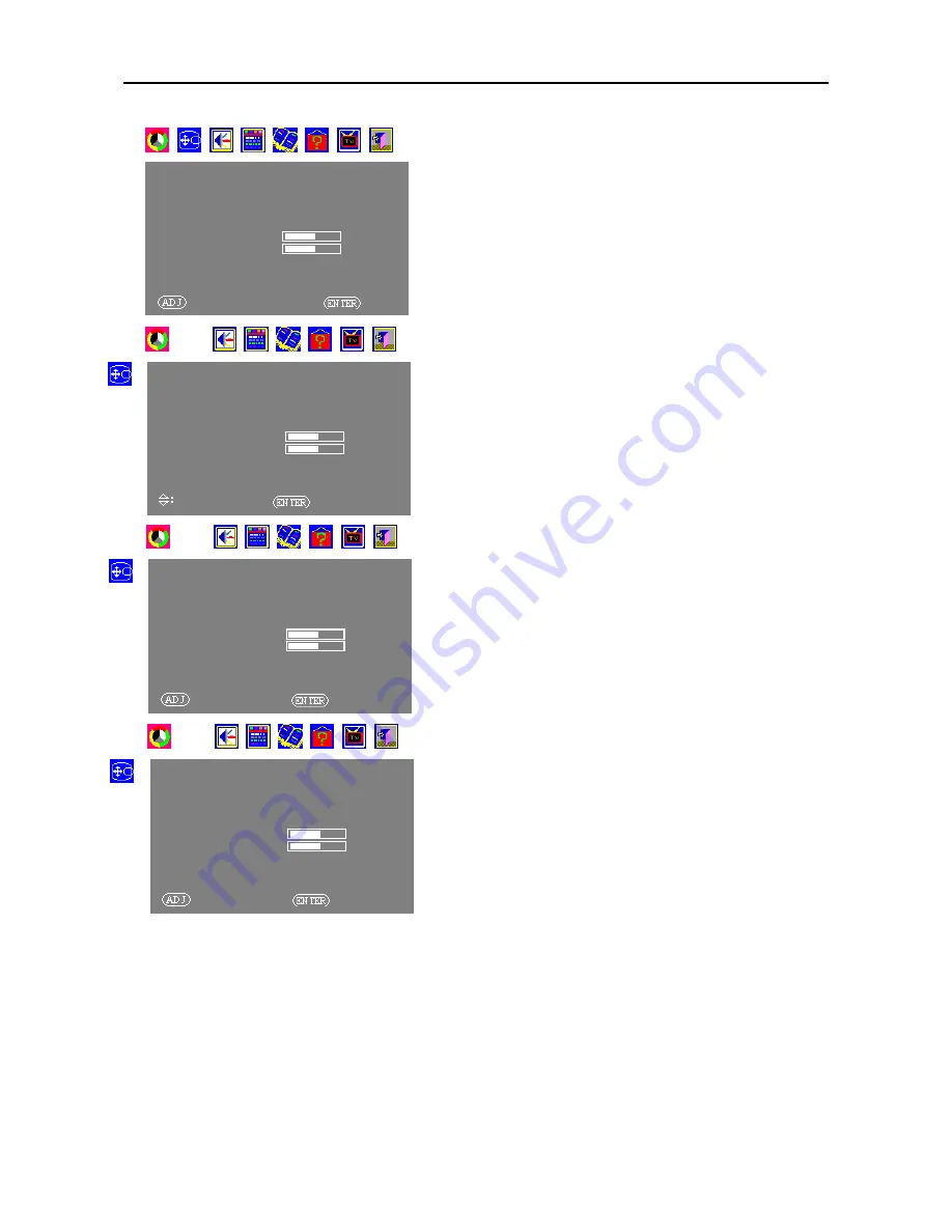
Press MENU button to display the menu operation interface 

on the screen. 

2.


Press ADJ+/ADJ- button to select Display menu and then 

press ENTER button. 

3.


Press ADJ+/ADJ- button to select the Display Mode under 

Display menu, and then press the ENTER button (now the 

Display Mode item glows red). 

4.


Press ADJ+/ADJ- button again to select PIP, and then press 

the ENTER button. PIP mode is displayed on the screen.   


You can also turn on PIP function by using remote control. 

Meanwhile, you can use the buttons on the remote control to 

operate more functions. 

Button name       Function Descriptions 

1


PIP   Turn 

on/off 

PIP/POP 

functions.  


2


VIDEO 

  Select 

the 

display 

mode 

of 

the 


   primary 

picture. 

3


PIP I/P   


Select the display mode of the   


   secondary 

picture. 

4


SWAP   


Switch between the primary and   


   secondary 

pictures. 


DISPLAY                   

POSITION                                                         
SIZE                                                     
PICTURE MODE                                            SINGLE 
PIP SETUP                                                                       
CLOCK                                 +000 
FOCUS                                                                      16 
AUTO FOCUS                         
EXIT MENU 
 

SELECT MAIN MENU    

OK 


DISPLAY                   

POSITION                                                         
SIZE                                                     

PICTURE MODE                                            SINGLE 

PIP SETUP                                                                       
CLOCK                                 +000 
FOCUS                                                                      16 
AUTO FOCUS                         
EXIT MENU 


SELECT ITEM   

OK 


DISPLAY                   

POSITION                                                         
SIZE                                                     

PICTURE MODE                                            SINGLE 

PIP SETUP                                                                       
CLOCK                                 +000 
FOCUS                                                                      16 
AUTO FOCUS                         
EXIT MENU 
 

ADJUSTMENT   

OK 


DISPLAY                   

POSITION                                                         
SIZE                                                     
PICTURE MODE                                            SINGLE

PIP SETUP                                                                       

CLOCK                                                                  +000
FOCUS                                                                      16 
AUTO FOCUS                         
EXIT MENU 
 

ADJUSTMENT   

OK 

Summary of Contents for PD4264

Page 1: ...eason 7 Important Safety Instruction 8 Introduction 10 Part Names and Function 11 Installation 15 Basic Operations 21 Wide Operations 22 OSD On Screen Display Controls 23 RS232C Control 31 Table of Si...

Page 2: ...ories and items are included y Whenever possible use the handles on the back of the TV for transport INSTALLATION y A specified technician from the distributor or authorised agent should always instal...

Page 3: ...mbols This symbol informs that there are contents that demand caution including warnings Concrete details of the caution are written within the diagram This symbol indicates a prohibited matter Concre...

Page 4: ...ing it at the top and bottom Failure to do so could cause the Plasma TV to fall resulting in injury Keep the product away from moisture Do not expose this appliance to rain or moisture If water penetr...

Page 5: ...revent such image sticking are Do not display images having sharp brightness differences or hi contrast images such as monochrome characters and graphic patterns for long Do not leave stationary image...

Page 6: ...thing type power outlet This is a safety feature if you are unable to insert the plug into the outlet contact an electrician Do not defeat the purpose of the earthing plug 8 Avoid overloading the powe...

Page 7: ...rating and maintenance servicing instructions in the literature accompanying the appliance Warning To prevent fire or shock hazard do not expose this appliance to rain or moisture Ventilation There sh...

Page 8: ...entilation For example the appliance should not be situated on a bed sofa rug or similar surface that may block the ventilation openings or placed in a built in situation such as a bookcase or cabinet...

Page 9: ...ge or other hazards Refer all servicing to qualified service personnel Overloading Do not overload wall outlets and extension cords as this can result in a risk of fire or electric shock Replacement P...

Page 10: ...y converts VGA SVGA XGA and SXGA signals to the panel s native resolution y Advanced DCDi Sampling Progressive Scan method is employed y RGB input 1 DVI input 1 Video input 2 S Video input 2 YPbPr inp...

Page 11: ...the signals from the remote control 4 INPUT Select Switches the input in the following order Video 1 S video 1 YPbPr RGB DVI TV YCbCr S video 2 Video 2 5 MENU Sets the on Screen Menu OSM mode and disp...

Page 12: ...lection and AUDIO MUTE and other controls are operated externally by external control See also page 31 for external control DVI 29pin INPUT Inputs a digital RGB signal TMDS D sub 15Pin INPUT Inputs th...

Page 13: ...en COMP Press this button to select component video source on MAIN screen YPbPr YCbCr YPbPr TV Switch to TV channel CHRTN At TV mode to exchange channel between currently channel and before channel At...

Page 14: ...The batteries of remote control may last approximately one year depending on how much the remote control is used For the best performance it is recommended the batteries of remote control be replaced...

Page 15: ...l Interface standard Use a DVI 29 pin signal cable when making connections to the DVI connector of the main unit Note that the DVI terminal does not support analog RGB input source Note 1 Input TMDS s...

Page 16: ...TV if your VCR or laser disc player has this capability Be careful to keep your right and left channel connections correct for stereo sound 3 Or use a standard S Video cable to connect the S Video Out...

Page 17: ...ower to your plasma TV 2 Connect one end of your coaxial cable to the RF input on your plasma TV 3 Turn on the plasma TV 4 Refer to TV Setup on page 30 You will be able view Cable or Air TV programs a...

Page 18: ...se a standard Audio cable to connect the Audio Output Connector of the DVD player to the Audio input terminals of the Plasma Multimedia TV relating to the Y Cb Cr or Y Pb Pr Video Input 4 Turn on the...

Page 19: ...ct attachable speakers directly to the plasma TV 1 Strip the ends of the speaker wires 2 Press down the tabs below the SPEAKERS terminals insert the speaker wire and release the tab to secure the spea...

Page 20: ...M D S Data 2 Shield 4 No Connection 5 No Connection 6 DDC Clock 7 DDC Data 8 No Connection 9 T M D S Data 1 10 T M D S Data 1 11 T M D S Data 1 Shield 12 No Connection 13 No Connection 14 5V Power 15...

Page 21: ...he POWER button on the remote control or the unit the TV s POWER STANDBY indicator will flash red LED until finishing store up data then to light up red LED and the standby mode is set then turn the m...

Page 22: ...kHz are in put Select an appropriate setting for RGB SELECT mode referring to the Table of Signals Supported on page 31 IBM PC AT and VGA are registered trademarks of IBM Inc of the United States The...

Page 23: ...selected item press the ENTER button again to make changes now the item glows red After the change is made press the ENTER button to exit the menu setup If no operation is detected the on screen menu...

Page 24: ...rightness Increase or decrease Contrast Sharpness Color Tint Color Temperature Select desired color temperature Normal cold warm 5 If you are satisfied with your setup press ENTER button again to comp...

Page 25: ...lay Mode item glows red 4 Press ADJ ADJ button again to select PIP and then press the ENTER button PIP mode is displayed on the screen You can also turn on PIP function by using remote control Meanwhi...

Page 26: ...to adjust and then press the ENTER button to enter the selected adjustment item now the item glows red 4 Adjustment Item Press ADJ ADJ Treble Increase or decrease Bass Increase or decrease Balance Inc...

Page 27: ...MENU button to display the menu operation interface on the screen 2 Press ADJ ADJ button to select Function menu and then press the ENTER button 3 Press ADJ ADJ button to select the item you want to...

Page 28: ...Configuration menu and then press the ENTER button now the Language option glows red 4 Press the ADJ ADJ button again to select the language you desire Then press the ENTER button to exit the Language...

Page 29: ...nterface on the screen 2 Press the ADJ ADJ button to select the Information menu The signal input information of the primary and secondary pictures will be displayed on the screen You can also use the...

Page 30: ...the setup the selected adjustment item glows green again When you use the PDP s TV function the first time we recommend channel scanning after selecting the required TV system This lets you to watch...

Page 31: ...G YES YES YES YES 72 8 37 9 NEG NEG YES YES YES YES 75 0 37 5 NEG NEG YES YES YES YES 85 0 43 3 NEG NEG YES YES YES YES 848 480 60 0 31 0 POS POS YES YES YES YES 852 480 60 0 31 7 NEG NEG YES YES YES...

Page 32: ...Is AUDIO INPUT set correctly ySet AUDIO INPUT on the SOUND menu correctly Poor picture with VIDEO signal input yImproper control setting Local interference Cable interconnections Input impedance is no...

Page 33: ...83 6lbs 38kg Environmental Considerations Operating Temperature Humidity 0 C to 40 C 32 F to 104 F 20 to 80 no condensation Storage Temperature Humidity 10 C to 50 C 14 F to 122 F 10 to 90 no condens...

Page 34: ...34...

Reviews: