13
TV Lock (Optional)
Lock the TV to prevent access to all channels.
Enter your password using numeric buttons, the [TV lock] menu appears.
Press the
▲
/
▼
button to select [Lock] or [Unlock].
Press OK.
Tips: 1. Switch the TV off and on again for the change to take effect.
2. If you select [Lock], you have to enter your password every time you turn on your TV.
Set Code
Follow the on-screen instruction to create or change your password using numeric buttons.
Tips: If forget your password, enter “8888” to override any existing codes.
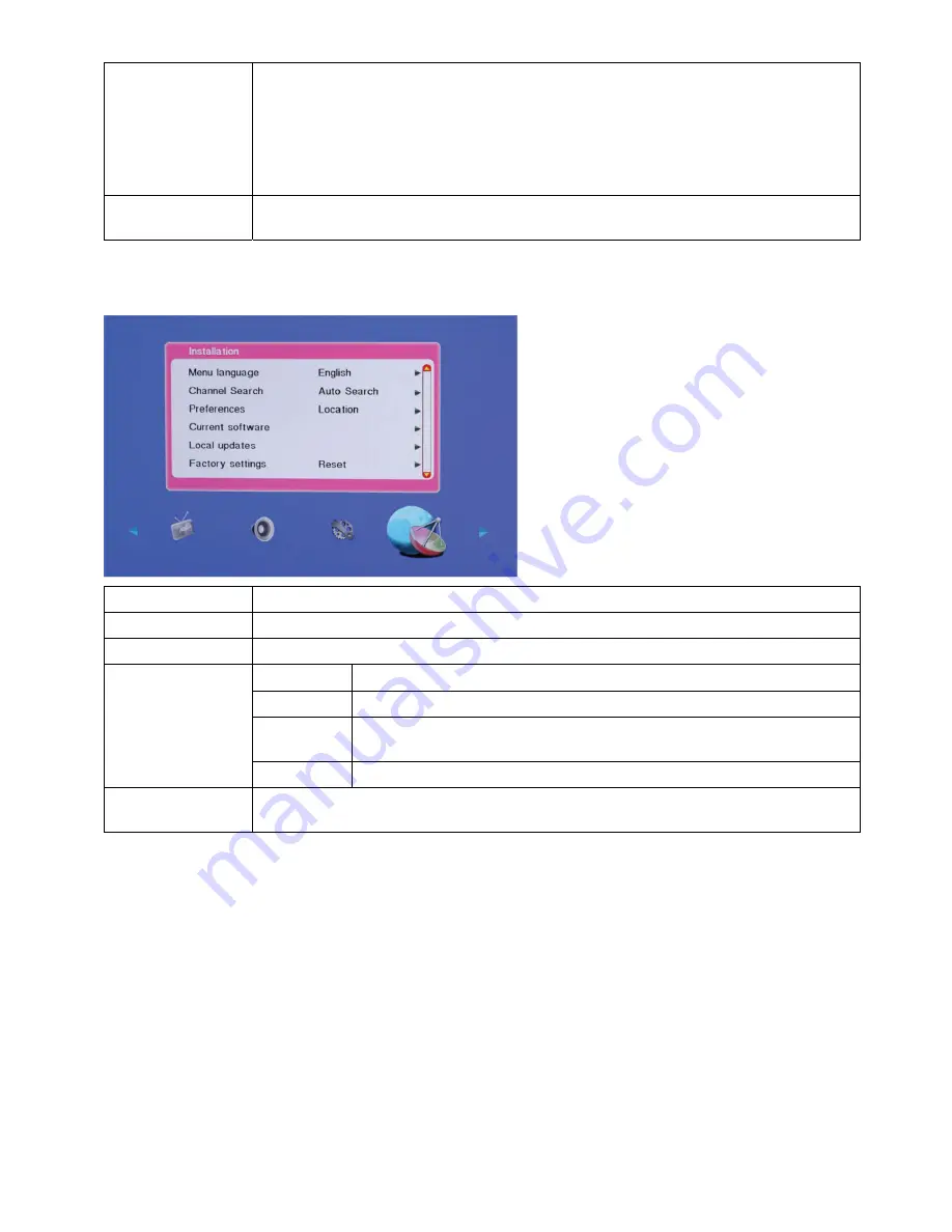
2.3.6 Installation Setting
Items Description
Menu Language
Press the
▲
/
▼
button to choose a required language and press the OK.
Channel Search
Please refer to channel search for details.
Location
Optimum TV settings for your location-home or shop.
Volume bar
We can display or hide the volume bar on screen display by selecting on/off.
E-link
(Optional)
Enables one-touch play and one-touch standby between CEC compliant
devices.
Preferences
E-label
For shop mode only, sets the location of the e-label.
Factory Settings
You can restore the default picture and sound settings of your TV.
The channel installation settings remain the same.
Channel Search
Channel search can be done in two ways:
1. Auto search:
TV automatically searches for the channel in the available frequency band.
2. Manual search:
Search for the channels manually and store it to the desired channel number. So you can store
the favorite together.
Note:
Make sure you have connected RF signal cable before performing channel search.
Auto Search:
1. Select installation
menu.
2. Select auto search and press OK key or
►
arrow key to tune channels automatically and store.
3. During auto searching press OK key to stop search. A dialog box is prompted to select [stop] or [continue]. To
stop searching select [stop] or to continue searching select [continue] and press OK key.
Summary of Contents for LE32W037M
Page 6: ...6 2 2 Remote Control Before you use the remote control please install the batteries ...
Page 21: ...21 3 2 Factory Preset Display Modes ...
Page 23: ...23 3 Disconnect all the connectors 4 Remove the screws to remove the AC cover and the boards ...
Page 32: ...32 6 PCB Layout 6 1 Main Board 715G4089M02000004F ...
Page 33: ...33 ...
Page 34: ...34 ...
Page 35: ...35 ...
Page 36: ...36 6 2 Power Board 715G4078P01W22003H ...
Page 37: ...37 ...
Page 38: ...38 6 3 Key Board 715G4224K01000004S 6 4IR Board 715G4086R01000004 ...
Page 40: ...40 8 Block Diagram ...
Page 41: ...41 ...
Page 58: ...58 10 Exploded View ...


