


7
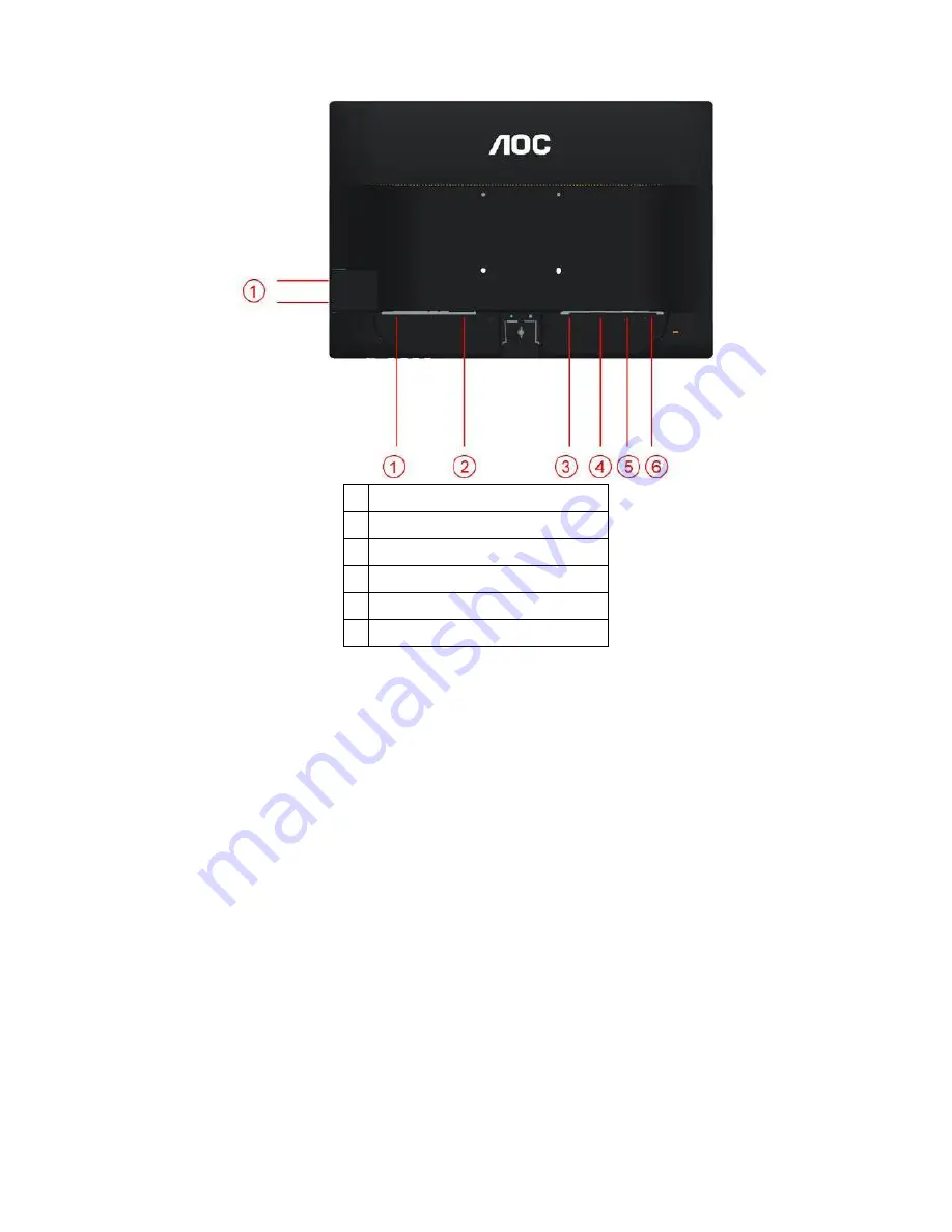
1 USB
2 Power
3 HDMI
4 DVI
5 Analog (DB-15 VGA cable)
6 Line in
To protect equipment, always turn off the PC and LCD monitor before connecting.
1 Connect the power cable to the AC port on the back of the monitor.
2 Connect one end of the 15-pin D-Sub cable to the back of the monitor and connect the other end to the computer's
D-Sub port.
3. Connect one end of the DVI cable to the back of the monitor and connect the other end to the computer
‟
s DVI
port.
4. (Optional
– Requires a video card with HDMI port) - Connect one end of the HDMI cable to the back of the monitor
and connect the other end to the computer
‟
s HDMI port.
5 Turn on your monitor and computer.
If your monitor displays an image, installation is complete. If it does not display an image, please refer
Troubleshooting.
Summary of Contents for e2260Phu
Page 4: ...4 1 Monitor Specifications ...
Page 9: ...9 Luminance ...
Page 10: ...10 ...
Page 11: ...11 ...
Page 12: ...12 Image Setup ...
Page 13: ...13 ...
Page 14: ...14 Color Setup ...
Page 15: ...15 ...
Page 16: ...16 Picture Boost ...
Page 17: ...17 ...
Page 18: ...18 OSD Setup ...
Page 19: ...19 ...
Page 20: ...20 Extra ...
Page 21: ...21 ...
Page 22: ...22 Exit ...
Page 23: ...23 LED Indicator Status LED Color Full Power Mode Green or Blue Active off Mode Orange or red ...
Page 24: ...24 4 Input Output Specification 4 1 Input Signal Connector Pin Assignments ...
Page 25: ...25 4 2 Factory Preset Display Modes ...
Page 27: ...27 4 3 4 Optical Characteristics Ta 25 2 ...
Page 46: ...46 7 PCB Layout 7 1 Main Board 715G5436M01000004C ...
Page 47: ...47 ...
Page 48: ...48 ...
Page 49: ...49 7 2 Power Board 715G5361P02000001S ...
Page 50: ...50 ...
Page 51: ...51 7 3 Key Board 715G5357K01000001S ...
Page 52: ...52 7 4 IR Board 715G5368T01000004C ...
Page 53: ...53 ...
Page 54: ...54 7 5 USB Board 715G5370T01000004S ...
Page 55: ...55 715G2727T01001001H ...
Page 63: ...63 10 Monitor Exploded View ...


