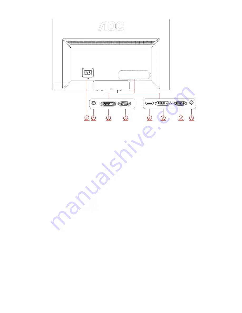
AOC e2050Swd Service Manual Download Page 7


1. AC port 

2. VGA 

3. DVI (available for selected models) 

4. HDMI(available for selected models) 

5. Audio(available for selected models)     


To protect equipment, always turn off the PC and LCD monitor before connecting.   

1. Connect the power cable to the AC port on the back of the monitor. 

2. Connect one end of the 15-pin D-Sub cable to the back of the monitor and connect the other end to the computer's 

D-Sub port. 

3. Optional 

–( Requires a video card with DVI port) - Connect one end of the DVI cable to the back of the monitor and 

connect the other end to the computer’s DVI port. 

4. Optional 

–( Requires a video card with HDMI port) - Connect one end of the HDMI cable to the back of the monitor 

and connect the other end to the computer’s HDMI port. 

5. Optional 

–(Requires a video card with Audio port) - Connect one end of the Audio cable to the back of the monitor 

and connect the other end to the computer’s Audio port.. 

6. Turn on your monitor and computer. 

If your monitor displays an image, installation is complete. If it does not display an image, please refer 

Troubleshooting. 

Summary of Contents for e2050Swd

Page 1: ...st 2 Important Safety Notice 3 1 Monitor Specification 4 2 LCD Monitor Description 5 3 Operation Instruction 6 3 1 General Instructions 6 3 2 Control Buttons and Connections 6 3 3 OSD Setting 8 4 Input Output Specification 18 4 1 Input Signal Connector 18 4 2 Preset Display Modes 19 4 3 Panel Specification 20 5 Block Diagram 22 5 1 Main Board 22 5 2 Power Board 23 6 Schematic 24 6 1 Main Board 24 ...

Page 2: ...2 Revision List Version Release Date Revision History TPV Model Name A00 Feb 17 2013 Initial release T9CMN26KAGACHNE T9CMN26MAGACHNE T9CMN26IAGACHNE T9CMN26VAGACHNE T9CMN26TAGACHNE T9CMN26XAGACHNE ...

Page 3: ...may create shock fire or other hazards Under no circumstances should the original design be modified or altered without written permission from AOC AOC assumes no liability express or implied arising out of any unauthorized modification of design Servicer assumes all liability FOR PRODUCTS CONTAINING LASER DANGER Invisible laser radiation when open AVOID DIRECT EXPOSURE TO BEAM CAUTION Use of cont...

Page 4: ...4 1 Monitor Specifications ...

Page 5: ...ss control logic and DDC The power part will provide AC to DC Inverter voltage to drive the backlight of panel and the main board chips each voltage Monitor Block Diagram AC IN 100V 240V Power Board Flat Panel and LED backlight Main Board RS232 Connector For white balance adjustment in factory mode LED Drive Video signal DDC HOST Computer Key Board ...

Page 6: ...vailable in all models Volume When there is no OSD Press Volume button to active volume djustment bar Press or to adjust volume Only for the models with speakers 4 3 or wide When there is no OSD Press continuously to change 4 3 or wide image ratio If the product screen size is 4 3 or input signal resolution is wide format the hot key is disable to adjust Auto Exit When there is no OSD press Auto E...

Page 7: ... video card with DVI port Connect one end of the DVI cable to the back of the monitor and connect the other end to the computer s DVI port 4 Optional Requires a video card with HDMI port Connect one end of the HDMI cable to the back of the monitor and connect the other end to the computer s HDMI port 5 Optional Requires a video card with Audio port Connect one end of the Audio cable to the back of...

Page 8: ...u want to adjust any other function repeat steps 2 3 4 OSD Lock Function To lock the OSD press and hold the MENU button while the monitor is off and then press power button to turn the monitor on To un lock the OSD press and hold the MENU button while the monitor is off and then press power button to turn the monitor on Notes 1 If the product has only one signal input the item of Input Select is d...

Page 9: ...9 Luminance 1 Press Menu to display menu 2 Press or to select Luminance and press to enter 3 Press or to select submenu and press to enter 4 Press or to adjust 5 Press to exit ...

Page 10: ...10 Image Setup 1 Press Menu to display menu 2 Press or to select Image Setup and press to enter 3 Press or to select submenu and press to enter 4 Press or to adjust 5 Press to exit ...

Page 11: ...11 Color Setup 1 Press Menu to display menu 2 Press or to select Color Setup and press to enter 3 Press or to select submenu and press to enter 4 Press or to adjust 5 Press to exit ...

Page 12: ...12 Picture Boost 1 Press Menu to display menu 2 Press or to select Picture Boost and press to enter 3 Press or to select submenu and press to enter 4 Press or to adjust 5 Press to exit ...

Page 13: ...13 OSD Setup 1 Press Menu to display menu 2 Press or to select OSD Setup and press to enter 3 Press or to select submenu and press to enter 4 Press or to adjust 5 Press to exit ...

Page 14: ...14 Extra 1 Press Menu to display menu 2 Press or to select Extra and press to enter 3 Press or to select submenu and press to enter 4 Press or to adjust 5 Press to exit ...

Page 15: ...15 Exit 1 Press Menu to display menu 2 Press or to select Exit and press to enter 3 Press or to select submenu and press to enter 4 Press or to adjust 5 Press to exit ...

Page 16: ...nstalling the e Saver software follow the install wizard to complete software installation Under each of the four PC status you may choose from the pull down menu the desired time in minutes for your monitor to automatically shutdown The example above illustrated 1 The monitor will never shutdown when the PC is powered on 2 The monitor will automatically shutdown 5 minutes after the PC is powered ...

Page 17: ...ng tool it splits the desktop into different panes each pane displays a different window You only need to drag the window to a corresponding pane when you want to access it It supports multiple monitor display to make your task easier Please follow the installation software to install it ...

Page 18: ...18 4 Input Output Specification 4 1 Input Signal Connector ...

Page 19: ...19 4 2 Preset Display Modes ...

Page 20: ...y module with WLED Backlight unit and 30 pins 2ch LVDS interface This module supports 1600 x 900 HD mode and can display up to 16 7M colors The converter module for Backlight is not built in 4 3 2 Display Characteristics 4 3 3 Electrical Characteristics TFT LCD MODULE Vcc 5 0 V Ta 25 2 º C Fr 75Hz ...

Page 21: ...21 Back Light Unit Ta 25 2 º C 4 3 4 Optical Characteristics ...

Page 22: ...0 AHS0 AVS0 DDCSCL1 DDCSDA1 EDID_WP VGA_CABLE_DET PA 0 9 5V EDID_WP RX0 RX1 RX0 RXC RX2 RX2 RXC RX1 DDCSCL2 DDCSDA2 DVI_CABLE_DET 5V EDID_WP DVI_HPD VCC3 3 VCC1 8 5V 02 INPUT 02 D SUB INPUT R0 R0 SOG_DET G0 G0 B0 B0 5V AHS0 AVS0 DDCSCL1 DDCSDA1 EDID_WP VGA_CABLE_DET 04 SCALER 04 SCALER Adj_BACKLIGHT on_BACKLIGHT Audio_EN Audio_DET PS_EN Panel_ON PB 0 9 PA 0 9 R0 R0 SOG_DET G0 G0 B0 B0 AHS0 AVS0 DD...

Page 23: ... Q801 ON OFF DIM L801 LED CN804 PWM Control OZ9998BGN U801 14 5V EMI filter Start Resistor R908 R911 PWM Control LD7576AGR U901 Bridge Rectifier and Filter Rectifier diodes Transformer T901 Feedback Circuit Regulator IC903 5V Photo coupler U902 Power Switch Q901 ...

Page 24: ...0R05 1 16W C111 NC 22pF 50V R114 4K7 1 16W 5 C110 47N16V BIN0 C107 47N16V R115 4K7 1 16W 5 R112 75 OHM 5 1 16W D101 BAV70 3 1 2 R109 0R05 1 16W C105 47N16V R101 100R 1 16W 5 R102 100R 1 16W 5 R126 2K2 1 16W 5 C113 100N 16V R106 100R 1 16W 5 R103 0R05 1 16W C109 5PF 50V R116 22K 1 16W 5 R110 0R05 1 16W R108 100R 1 16W 5 R125 2K2 1 16W 5 C102 47N16V R107 75 OHM 5 1 16W R117 0R05 1 16W ZD101 RLZ5 6B ...

Page 25: ... 1 16W 5 R136 10R 1 16W 5 R134 10R 1 16W 5 U107 AOZ8902CIL CH1 1 VN 2 CH2 3 CH3 4 VP 5 CH4 6 D102 BAV70 3 1 2 R139 10R 1 16W 5 R135 10R 1 16W 5 C115 100N 16V C118 100N 16V R131 4K7 1 16W 5 ZD102 RLZ5 6B C116 220N16V R132 4K7 1 16W 5 R141 10R 1 16W 5 R127 100R 1 16W 5 R138 10R 1 16W 5 RX1 5 RX0 5 RX1 5 RXC 5 RX2 5 RX0 5 RXC 5 EDID_WP 3 5 RX2 5 DVI_CABLE_DET 5 DDCSDA2 5 5V 3 5 7 DDCSCL2 5 5V DVI5V D...

Page 26: ...54 T7M 53 T7P 52 PA1 PWMD DBC 34 PA2 PWMD DBC 84 PA0 PWMC 33 OSCO 93 OSCI 94 PC5 100 PC4 99 PC1 LPD_OUT 96 PC0 PWMA DBC 76 DVDD 23 CVDD_1V8 39 PE1 LPD_IN1 INT_VSO 78 DGND 77 PA3 85 SPI_CLK 86 SPI_SI 88 SPI_SO 87 SPI_CE 89 PC7 91 PA4 INTE3 INT_HSO 40 PA7 80 PA6 PWMC 81 PA5 PWMB 41 PB0 ADC0 35 PB1 ADC1 36 DVDD 73 PE0 PWMA LPD_IN0 29 PB3 ADC3 INTE1 82 PE3 PWMB 79 PE2 PWMA DBC 42 OSC_GND 95 R441 NC 4K...

Page 27: ...ronics Co Ltd Key Component 絬 隔 瓜 絪 腹 DUAL B OTS A 6 7 Friday October 29 2010 715G4502 M0B 000 0040 称爹 LVDS PANEL I O 715G4502 M0B 000 0040 C433 100uF16V FB409 120 OHM 1 2 R449 300 OHM 1 4W CN409 NC CONN 2 4 6 8 10 12 14 16 18 20 22 24 26 28 30 1 3 5 7 9 11 13 15 17 19 21 23 25 27 29 C436 NC C435 NC PA9 LVA0M CN408 CONN 1 2 3 4 5 6 7 8 9 10 11 12 13 14 15 16 17 18 19 20 21 22 23 24 25 26 27 28 29 ...

Page 28: ...4 VIN 3 VOUT 2 GND 1 C715 220N16V U701 AZ1117H 3 3TRG1 INPUT 3 ADJ GND 1 OUTPUT 2 4 4 on_BACKLIGHT 5 Adj_BACKLIGHT 5 VCC3 3 5 VLCD 6 VCC1 8 5 5V 3 4 5 Audio_EN 5 Panel_ON 5 5V 3 4 5 VLCD VCC3 3 5V VCC3 3 5V VCC3 3 5V VCC3 3 5V VCC1 8 5V U702 NC G1117 33T43UF ADJ GND 1 VOUT TAB 2 VIN 3 OEM MODEL Size Rev Date Sheet of TPV MODEL PCB NAME 称爹 T P V Top Victory Electronics Co Ltd Key Component 絬 隔 瓜 絪 ...

Page 29: ...00K C922 470uF 16V C924 0 1uF 50V R914 NC D908 NC IN4148 R933 NC R905 470OHM 5 1 8W C927 47N 50V R904 250OHM2W D902 SR515 FB903 BEAD 1 2 R919 220 OHM 1 8W D901 SR515 C923 1nF 50V R917 10 OHM 1 4W R910 100 OHM 1 4W R920 2K 1 8W R909 100 OHM 1 4W T901 POWER X FMR 1 3 4 5 6 7 8 9 10 11 12 C908 0 47UF Q901 P0765ATF C928 2N2 500V U902 PC123X2YFZOF 1 2 4 3 U901 LD7576AGR CT 1 COMP 2 CS 3 GND 4 OUT 5 VCC...

Page 30: ...EF 8 VIN 9 STATUS 10 SSTCMP 11 PWM 12 C813 100PF 50V R812 0 1R 1 R818 10K 1 8W R813 0 1R 1 D801 SK310B 1 2 R814 10 OHM 1 1 4W C807 220N 50V R803 300K 1 8W C811 0 47UF 50V Q801 APM8005KCTRG S1 1 G1 2 S2 3 G2 4 D2 5 D2 6 D1 7 D1 8 R817 100 OHM 1 4W C803 1N 50V C805 1UF 25V L801 47UH CN804 CONN 1 2 3 4 5 6 7 8 FB802 BEAD 1 2 C806 220N 50V R810 18K 1 8W 1 R816 7 5K OHM 1 C814 100N 50V C815 1N 50V FB80...

Page 31: ...Date Sheet of TPV MODEL PCB NAME 称爹 T P V Top Victory Electronics Co Ltd Key Component 絬 隔 瓜 絪 腹 e950Sw B N A B 2 2 Tuesday Nov ember 02 2010 715G4747 称爹 2 0 key G4747 K0B 000 0040 101026 SW002 SW SW003 SW SW001 SW SW004 SW R003 2KOHM 1 1 10W R002 0R01 1 10W C001 NC 0 1uF 50V R001 2KOHM 1 1 10W SW005 SW C002 NC 0 1uF 50V R004 1K 1 10W DOWN LBADC1 1 118V 0 673V 1K CN001 Wire Harness 1 2 3 4 5 6 SGN...

Page 32: ...32 7 PCB Layout 7 1 Main Board 715G4502M01000004I ...

Page 33: ...33 ...

Page 34: ...34 7 2 Power Board 715G4744P01003001M ...

Page 35: ...35 V ...

Page 36: ...36 7 3 Key Board 715G4747K02000001C ...

Page 37: ...intainability 8 1 Equipments and Tools Requirement 1 Voltmeter 2 Oscilloscope 3 Pattern Generator 4 DDC Tool with an IBM Compatible Computer 5 Alignment Tool 6 LCD Color Analyzer 7 Service Manual 8 User Manual ...

Page 38: ... is tightened Check Power On Off is On Re plug the power cable Replace main board and check connections Check the LED indicate is OK Check the AC power Replace the converter board OK NG OK NG NG Turn on the Power On Off switch Replace key board and check connections NG ...

Page 39: ...ue Press the power button is OK Check the LVDS FFC cable or panel The end NG OK OK NG Replace the main board Replace the converter board Replace the LVDS FFC cable or panel NG The end Replace the key board NG OK Replace the main board and connection OK ...

Page 40: ...ry mode Set to the optimal frequency select the recommended frequency Pull out signal cable and check Self Test Feature Check is ok Check the signal cable and the PC Readjust the phase and pixel clock in the user mode Replace the main board Replace the panel NG NG NG OK NG NG OK The end OK NG ...

Page 41: ...r shift Replace the signal cable Pull out the signal cable and check the screen color display is normal The end Replace the signal cable or PC Reset the factory mode In the user mode set the color settings until customer satisfy Replace the main board NG OK NG OK NG ...

Page 42: ...120 to RGB Mode with press MODE button 2 Switch the MEM channel to Channel 3 with up or down arrow on chroma 7120 3 The LCD indicator on chroma 7120 will show x 313 20 y 329 20 4 Adjust the RED on factory window until chroma 7120 indicator reached the value R 100 5 Adjust the GREEN on factory window until chroma 7120 indicator reachedthe value G 100 6 Adjust the BLUE on factory window until chroma...

Page 43: ...bove procedure item 4 5 6 until chroma 7120 RGB value meet the tolerance 100 2 D Adjust sRGB color temperature 1 Switch the chroma 7120 to RGB Mode with press MODE button 2 Switch the MEM channel to Channel 10 with up or down arrow on chroma 7120 3 The LCD indicator on chroma 7120 will show x 313 20 y 329 20 4 Adjust the RED on factory window until chroma 7120 indicator reached the value R 100 5 A...

Page 44: ...Y 1 3 A33G1182 1 POWER LENS 1 4 Q52G1801MNT160CF LT MYLAR 1 5 A15G1586 MAIN FRAME 1 6 A15G1587101 HINGE PLATE 2 7 Q34G7637ABJ REAR COVER 1 8 A37G0241013 HINGE 1 9 A33G1183ABJ STAND 1 10 A34G2530ABJ STAND COVER 1 11 A34G2531AED BASE 1 12 Q12G6600 6 RUBBER FOOT 4 13 A33G1184ABJ HINGE COVER 1 ...

Page 45: ...L0100 STAND_TOP A33G1184ABJ 1L0100 COVER_HINGE A34G2530ABJ 1B0100 COVER_STAND A34G2531AED01B0130 BASE A37G0241013 HINGE 20 AM1G1740 10125 SCREW H40G 001624 1A CARTON LABEL BARCODE 1 H40G020N61558A RATING LABEL e2050SW EPI H40G045762413C OTHER LABEL base PN LABEL H44GA016101 CUSHION T H44GA016201 CUSHION B H44GA01661509A00HX ARTWORK CARTON E2050SW 19 5 H70G21C161511A CD MANUAL for 50s all Models KE...

Page 46: ...D909 093G 60519 DIODE SR560 MK23 5A 60V DO 27 SECOS D905 093G 60519 DIODE SR560 MK23 5A 60V DO 27 SECOS CN902 095G 825 9D905 HARNESS 9P SCN 9P 80mm FQE100911I CN804 311GW200A06ABX WAFER 2 0mm 6P D801A 393G0060A0400T SCHOTTKY SR310 29 X0 3A 100V High 6mm 705GHA57006 Q901 ASS Y 709G4744 HM001 CONSUMPTIVE ASS Y H40G 45762429A LABEL Q55G 100625 TIN STICK_LOW ARGENTUM C702 067G 3051013PB EC 105C 100uF ...

Page 47: ... FENGHUA R912 061G1206101 JT RST CHIPR 100 OHM 5 1 4W TZAI YUAN R929 061G1206101 JT RST CHIPR 100 OHM 5 1 4W TZAI YUAN R909 061G1206101 JT RST CHIPR 100 OHM 5 1 4W TZAI YUAN R903 061G1206101 JT RST CHIPR 100 OHM 5 1 4W TZAI YUAN R910 061G1206101 JT RST CHIPR 100 OHM 5 1 4W TZAI YUAN R930 061G1206101 JT RST CHIPR 100 OHM 5 1 4W TZAI YUAN R911 061G1206103 JF RST CHIPR 10KOHM 5 1 4W FENGHUA R908 061G...

Page 48: ...RE J811 095G 90 23 JUMP WIRE J812 095G 90 23 JUMP WIRE J813 095G 90 23 JUMP WIRE J814 095G 90 23 JUMP WIRE J815 095G 90 23 JUMP WIRE J901 095G 90 23 JUMP WIRE J902 095G 90 23 JUMP WIRE J903 095G 90 23 JUMP WIRE J904 095G 90 23 JUMP WIRE J905 095G 90 23 JUMP WIRE J906 095G 90 23 JUMP WIRE J907 095G 90 23 JUMP WIRE J909 095G 90 23 JUMP WIRE J910 095G 90 23 JUMP WIRE J921 095G 90 23 JUMP WIRE CN901 0...

Page 49: ...R E1 1A 3 3V TO 252 U104 056G 662 52 ESD PROTECT AZC398 04S R7G SOT23 6 U107 056G 662 52 ESD PROTECT AZC398 04S R7G SOT23 6 U106 056G 662 52 ESD PROTECT AZC398 04S R7G SOT23 6 U103 056G 662 52 ESD PROTECT AZC398 04S R7G SOT23 6 U102 056G 662 52 ESD PROTECT AZC398 04S R7G SOT23 6 U101 056G1133 34 1 EEPROM M24C02 RMN6TP 2Kb SO 8 U105 056G1133 34 1 EEPROM M24C02 RMN6TP 2Kb SO 8 U402 056G2233501 FLASH...

Page 50: ...YUAN R102 061G0402101 JT RST CHIP 100R 1 16W 5 TZAI YUAN R101 061G0402101 JT RST CHIP 100R 1 16W 5 TZAI YUAN R488 061G0402102 JT RST CHIP 1K 1 16W 5 TZAI YUAN R487 061G0402102 JT RST CHIP 1K 1 16W 5 TZAI YUAN R424 061G0402102 JT RST CHIP 1K 1 16W 5 TZAI YUAN R130 061G0402102 JT RST CHIP 1K 1 16W 5 TZAI YUAN R425 061G0402103 JT RST CHIP 10K 1 16W 5 TZAI YUAN R427 061G0402103 JT RST CHIP 10K 1 16W 5...

Page 51: ... 100NF 10 16V X7R C417 065G040210412K Y CAP 0402 100NF 10 16V X7R C418 065G040210412K Y CAP 0402 100NF 10 16V X7R C419 065G040210412K Y CAP 0402 100NF 10 16V X7R C422 065G040210412K Y CAP 0402 100NF 10 16V X7R C424 065G040210412K Y CAP 0402 100NF 10 16V X7R C425 065G040210412K Y CAP 0402 100NF 10 16V X7R C427 065G040210412K Y CAP 0402 100NF 10 16V X7R C434 065G040210412K Y CAP 0402 100NF 10 16V X7...

Page 52: ...250931C Y CAP 0402 5PF 0 25pF 50V NP0 C423 065G0805475A2K Y NO SUGGEST CAP 0805 4 7UF 10 10V X7R C421 065G0805475A2K Y NO SUGGEST CAP 0805 4 7UF 10 10V X7R C416 065G0805475A2K Y NO SUGGEST CAP 0805 4 7UF 10 10V X7R C413 065G0805475A2K Y NO SUGGEST CAP 0805 4 7UF 10 10V X7R C404 065G0805475A2K Y NO SUGGEST CAP 0805 4 7UF 10 10V X7R C401 065G0805475A2K Y NO SUGGEST CAP 0805 4 7UF 10 10V X7R FB407 07...

Reviews: