AOC 171S+ Service Manual Download Page 6


AOC 171S/171S+   

6                                                                                                                     

3. Operating Instructions 

3.1 General Instructions 

Press the power button to turn the monitor on or off. The other control buttons are located in front panel of the 

monitor. By changing these settings, the picture can be adjusted to your personal preferences. 


The power cord should be connected. 


Connect the video cable from the monitor to the video card. 


Press the power button to turn on the monitor position. The power indicator will light up. 

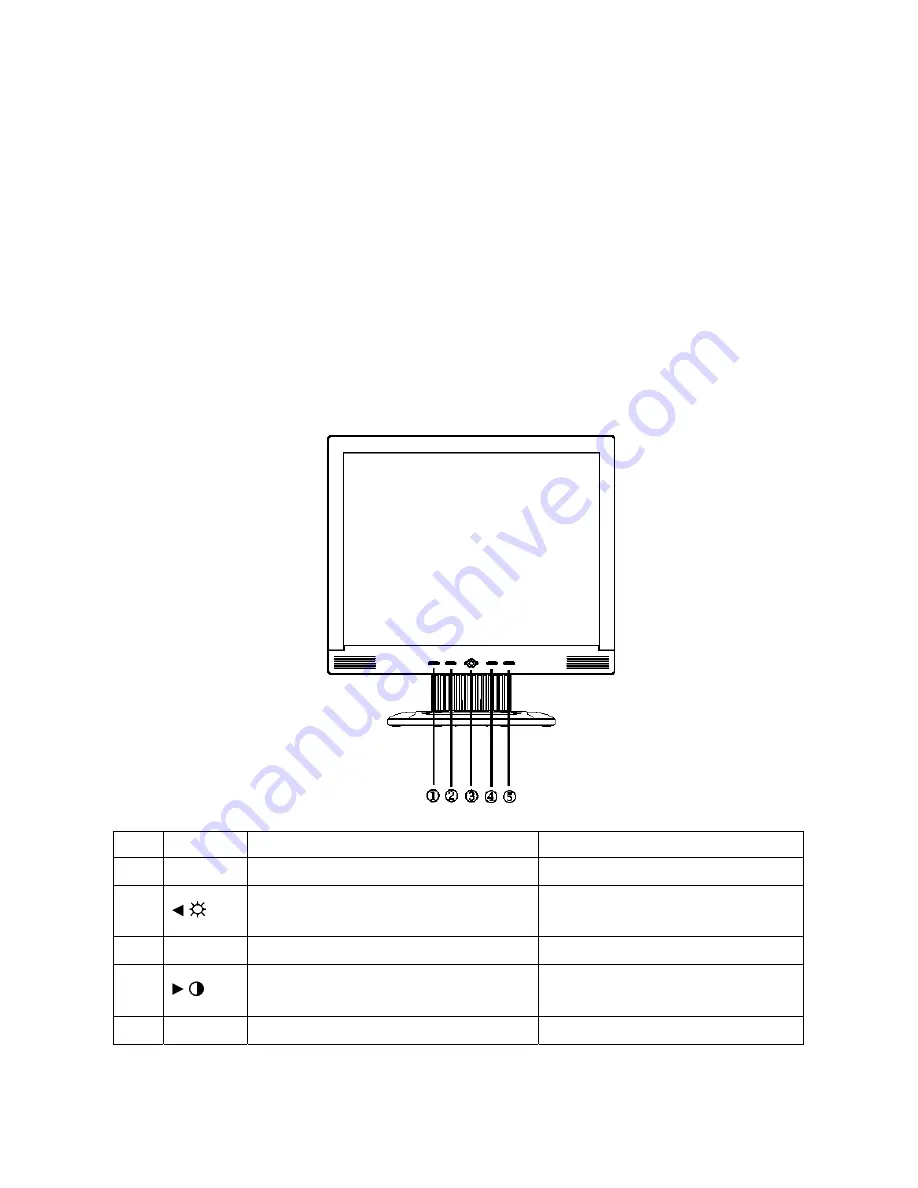
3.2 Front Panel Control 

- Auto 

Adjust 

Key: 

The Auto Adjust Key is used to automatically set the H Position, V Position, Clock and Phase. 

-


Power Indicator: 

Green  — Power On mode. 

Orange  — Power Saving mode. 


NO.  Name 

Within OSD 

Without OSD 

1 Auto/Exit Exit OSD or back to previous menu


Auto configuration


/


1.Move the cursor to left   

2. Decrease the value of the selected item 

Activate the brightness menu   

3 Power  Power On / Off 

Power On / Off 

/


1.Move the cursor to right   

2. Increase the value of the selected item 

Activate the contrast menu 

5 MENU  Select Function or select Sub menu


Activate OSD main menu


Summary of Contents for 171S+

Page 1: ...REPAIR SERVICE INFORMATION ONLY EVERY REASONABLE EFFORT HAS BEEN MADE TO ENSURE THE ACCURACY OF THIS MANUAL WE CANNOT GUARANTEE THE ACCURACY OF THIS INFORMATION AFTER THE DATE OF PUBLICATION AND DISCL...

Page 2: ...y Characteristics 11 4 4 3 Optical Characteristics 13 4 4 4 Electrical Characteristics 14 5 Block Diagram 16 5 1 Monitor Explored View 16 5 2 Software Flow Chart 17 5 3 Electrical Block Diagram 19 5 3...

Page 3: ...AOC 171S 171S 3 Revision List Version Date Revision History TPV Model Name T780KC4MDAACM A00 Mar 17 06 Initial Revision T780KV4MDAACM...

Page 4: ...5 Pin Analog H Frequency 30kHz 80kHz Input V Frequency 55 75Hz ON Mode 45W Power Consumption OFF Mode 2W Display Color 16 2M 6 Bit FRC for 171S 16 77M colors 6bit FRC for 171S Contrast Ratio 500 1 for...

Page 5: ...control logic and DDC The power board will provide AC to DC Inverter voltage to drive the backlight of panel and the main board chips each voltage HOST Computer AC IN 100V 240V PWPC board Include adap...

Page 6: ...The power indicator will light up 3 2 Front Panel Control Auto Adjust Key The Auto Adjust Key is used to automatically set the H Position V Position Clock and Phase Power Indicator Green Power On mod...

Page 7: ...horizontal position of the picture 0 100 Do Auto Config Image Position V Position Adjust the vertical position of the picture 0 100 Do Auto Config Warm N A Recall Warm Color Temperature from EEPROM N...

Page 8: ...language to French N A Espa ol N A Set OSD display language to Spain N A Italiano N A Set OSD display language to Italian N A Language N A Set OSD display language to Simplified Chinese N A The Langua...

Page 9: ...Signal Connector Pin No Description Pin No Description 1 Red 9 5V 2 Green 10 Detect Table 3 Blue 11 Ground 4 Ground 12 DDC Serial Data 5 Ground 13 H Sync 6 R Ground 14 V Sync 7 G Ground 15 DDC Serial...

Page 10: ...5Hz 1056x625 46 875 P 75 000 P 49 500 1024x768 60Hz 1344x806 48 363 N 60 004 N 65 000 1024x768 70Hz 1328x806 56 476 N 70 069 N 75 000 XGA 1024x768 75Hz 1312x800 60 023 P 75 029 P 78 750 1280x1024 60Hz...

Page 11: ...h a maximum of 1 half wave missing per second DC output Voltage 12VDC 5 4 4 Panel Specification 4 4 1 Panel Feature for 171S a Si TFT active matrix LVDS interface R G B input 8bit 16 77 millions color...

Page 12: ...AOC 171S 171S 12 for 171S...

Page 13: ...ntal 80 80 85 85 Vertical CR 5 80 80 85 85 Horizontal 60 60 70 70 Viewing Angle Vertical CR 10 60 55 67 63 White Wx Wy 0 283 0 299 0 313 0 329 0 343 0 359 Red Rx Ry 0 614 0 308 0 644 0 338 0 674 0 368...

Page 14: ...AOC 171S 171S 14 for 171S 4 4 4 Electrical Characteristics 1 TFT LCD Module for 171S...

Page 15: ...AOC 171S 171S 15 for 171S 2 Back Light Unit for 171S for 171S...

Page 16: ...AOC 171S 171S 16 5 Block Diagram 5 1 Monitor Exploded View...

Page 17: ...AOC 171S 171S 17 5 2 Software Flowing Chart 1 2 N Y 5 Y N 10 Y N 12 Y N 7 Y N 6 4 3 8 9 14 11 13 Y N 15 Y N 16 17 19 Y N 18...

Page 18: ...ED and set it to green color Scalar initialize 10 In standby mode 11 Update the lifetime of back light 12 Check the analog port are they re any signals coming 13 Does the scalar send out an interrupt...

Page 19: ...n Board MCU W78E65 U601 Scalar IC TSU16AK Include ADC OSD U401 EEPROM 24LC16B U602 EEPROM M24C02 U301 H sync V sync RGB DB15_SDA DB15_SCL EPR_SDA EPR_SCL LCD Interface CN503 Key Board Control D Sub Co...

Page 20: ...dge Rectifier and Filter Start Circuit R906 R907 PWM Control IC Transformer Rectifier diodes AC input 12V ON OFF Control PWM Control IC Feedback Circuit OSC and Output Circuit DC Convert Circuit MOSFE...

Page 21: ...T_DET1 SCL HWRESET DDC_CLK Volume VCC5V VCC12V VCPU RXD TXD AD0 AD1 AD2 AD3 VCC5V B5 5 PANEL INTERFACE VLCD PB 0 9 PA 0 9 VAA4 PB 0 9 VLCD B4 2 POWER onPanel_5V 3 3V onBACKLITE AdjBACKLITE VCC3 3 VCC2...

Page 22: ...F R214 delete CN201 CONN 2 4 6 8 10 12 1 3 5 7 9 11 R209 0 1 16W VCC5V VLCD 5 FB201 600 OHM ON_OFF VCC5V C208 100uF 16V R202 10K 1 16W DIM R205 4 7K 1 16W R203 1K 1 16W onPanel_5V 3 3V 6 VCC3 3 4 VCPU...

Page 23: ...04 0 047uF HSYNC 4 CLK_DDC2 D316 LL5232B 5 6V 5 BIN 4 ST_DET1 6 R305 100 1 16W TXD 6 R327 75 1 16W DDC_CLK 6 DVI5V D319 TZMC5V6 GS08 D301 BAV99 3 1 2 R313 2 2K 1 16W GIN 4 R301 100 1 16W R326 75 1 16W...

Page 24: ...A1P LVA1M LVA0P LVA0M NC LVB3P NC LVB3M NC LVBCKP NC LVBCKM NC LVB2P NC LVB2M NC LVB1P NC LVB1M NC LVB0P NC LVB0M DDC1_CLK GPO8 DDC1_DAT GPO7 ADO NC AD3 NC AVDD_PLL AVDD AVSS AVSS_DVI LVACKP LVA3M LVA...

Page 25: ...LVACKP LVA2M LVBCKM RXO0 C509 47uF 16V LVA2P RXO2 PB9 RXO2 RXOC LVBCKP PB4 PANEL INTERFACE D A 5 6 Wednesday April 14 2004 Title Size Document Number Rev Date Sheet of LVB0M LVA3M RXEC LVB1P RXO3 PB2...

Page 26: ...1 3 5 7 9 11 13 15 CSZ 4 VCC5V 2 3 4 C615 NC AD0 4 R610 NC U601 W78E65P 40 35 21 20 10 14 15 16 17 2 3 4 5 6 7 8 9 43 42 41 40 39 38 37 36 24 25 26 27 28 29 30 31 19 18 32 33 13 11 22 44 12 EA VP XTAL...

Page 27: ...AOC 171S 171S 27 6 2 Power Board 715L1103 217A...

Page 28: ...AOC 171S 171S 28...

Page 29: ...AOC 171S 171S 29 7 PCB Layout 7 1 Main Board 715L1237 1 3...

Page 30: ...AOC 171S 171S 30 7 2 POWER BOARD 715L1103 217A 7 3 Key Board 715L1222 B...

Page 31: ...1 8 Maintainability 8 1 Equipments And Tools Requirement 1 Voltmeter 2 Oscilloscope 3 Pattern Generator 4 DDC Tool with an IBM Compatible Computer 5 Alignment Tool 6 LCD Color Analyzer 7 Service Manua...

Page 32: ...icture is normal Please reinsert and make sure the AC of 100 240 is normal Measure U201 PIN2 2 5V U202 PIN2 3 3V Reinsert or check the Adapter Inverter section X601 and X401 oscillate waveforms are no...

Page 33: ...ace U601 Replace X601 Measure U201 PIN2 2 5V U202 PIN2 3 3V Check Correspondent component Replace U401 X401 oscillate waveform is normal Replace U201 U202 OK OK OK OK OK NG NG NG NG Check reset circui...

Page 34: ...04 base is low level X601 oscillate waveform is normal Check Q204 is broken or CN503 solder Check Correspondent component Replace PANEL Check Correspondent component Replace U601 OK OK OK Replace X601...

Page 35: ...of C905 Check bridge rectified circuit and F901 circuit Check start voltage for the pin3 of IC901 Check R906 R907 and Change IC901 NG Check the auxiliary voltage is bigger than 10V and smaller than 20...

Page 36: ...ge Q201 or Q202 Check U201 PIN10 7 have the output of sawtooth wave at short time NG OK Change U201 Check D201 D202 have the output of square wave at short time NG OK Check Q205 Q206 Q207 Q208 Q203 Q2...

Page 37: ...ypad Board OSD is unstable or not working Is Key Pad Board connecting normally Connect Key Pad Board Is Button Switch normally Replace Button Switch Y N N Is Key Pad Board normally Replace Key Pad Boa...

Page 38: ...e MEM Channel to Channel 3 with up or down arrow on chroma 7120 3 The LCD indicator on chroma 7120 will show x 296 20 y 311 20 Y 180 cd m2 4 Adjust the RED of color1 on factory window until chroma 712...

Page 39: ...3 68 22 1B 78 2A 38 8F A3 58 46 9D 24 32 17 4C 55 BF EF 00 81 80 01 01 01 01 01 01 01 01 48 01 01 01 01 01 01 30 2A 00 98 51 00 2A 40 30 70 64 13 00 78 2D 11 00 00 1E 00 00 00 FF 00 32 33 31 80 35 34...

Page 40: ...L 1 PCS for 171S 40G 58162435A LABEL 1 PCS 41G700N61580B MANUAL 1 PCS for 171S 41G700A615A17 MANUAL 1 PCS for 171S 41G780061585C WARRANTY CARD 1 PCS 44G3739 1 EPS L 1 PCS 44G3739 2 EPS R 1 PCS 44G3739...

Page 41: ...A07 1V CPT 17 110 V PANEL 1 PCS for 171S 750LLD701TB11V SVA 17 1TB V PANEL 1 PCS for 171S 705L782KB34141 for 171S 33G4693 Q1 L KEY PAD 1 PCS 33G4694 1 C POWER LENS 1 PCS 33G4695 1 C CLAMP 1 PCS 34G127...

Page 42: ...65G0603104 32 CHIP 0 1UF 50V X7R 1 PCS C214 65G0603104 32 CHIP 0 1UF 50V X7R 1 PCS C216 65G0603104 32 CHIP 0 1UF 50V X7R 1 PCS C217 65G0603104 32 CHIP 0 1UF 50V X7R 1 PCS C304 65G0603473 32 CHIP 0 047...

Page 43: ...65G0603104 32 CHIP 0 1UF 50V X7R 1 PCS C510 65G0603104 32 CHIP 0 1UF 50V X7R 1 PCS C511 65G0603104 32 CHIP 0 1UF 50V X7R 1 PCS C601 65G0603104 32 CHIP 0 1UF 50V X7R 1 PCS C602 65G0603220 31 CER1 0603...

Page 44: ...3 1 A03401 SOT23 BY AOS A1 1 PCS Q204 57G 417 4 PMBS3904 PHILIPS SMT 04 1 PCS Q601 57G 417 6 PMBS3906 PHILIPS SMT 06 1 PCS Q602 57G 417 6 PMBS3906 PHILIPS SMT 06 1 PCS R201 61L0603472 RST SM 0603 RC06...

Page 45: ...SM 0603 RC0603 100R 1 PCS R403 61L0603390 0F CHIP 390 OHM 1 10W 1 1 PCS R404 61L0603103 RST SM 0603 RC0603 10K 1 PCS R405 61L0603103 RST SM 0603 RC0603 10K 1 PCS R406 61L0603103 RST SM 0603 RC0603 10K...

Page 46: ...PCS U601 56G1125137CE9 W78E65P 40 1 PCS U602 56G113356A 24LC16B SNG SOIC 8PIN 1 PCS U603 56G 643 9 EM6353BZ2SP38 2 9 1 PCS KEPC780KAC 715L1222 B PCB 1 PCS CN101 33G801712A H PIN HEADER 2 6 R A 1 PCS...

Page 47: ...1 PCS L201 73G 253515 S CHOLE 1 PCS L202 73G 253515 S CHOLE 1 PCS L903 73G 253 91 H CHOKE COIL 1 PCS L904 73G 253 91 H CHOKE COIL 1 PCS NR901 61G 58080 WT 8 OHM NCT 1 PCS Q209 57G 761 6 2SC5706 P E 1...

Page 48: ...R213 61L0603392 CHIP 3 9K OHM 1 10W 1 PCS R216 61L0603221 RST SM 0603 RC0603 220R 1 PCS R217 61L0603221 RST SM 0603 RC0603 220R 1 PCS R224 61L1206152 CHIPR 1 5K OHM 5 1 4W 1 PCS R225 61L1206152 CHIPR...

Page 49: ...514HT LOW ESR 150UF 25V 8 7MM 1 PCS C204 64G700J1040AT 0 1UF 50V PEN 1 PCS C205 64G700J1040AT 0 1UF 50V PEN 1 PCS C206 64G700J1040AT 0 1UF 50V PEN 1 PCS C207 67G 305479 7T 4 7UF 20 50V 105 1 PCS C208...

Page 50: ...FR 10KOHM 5 1 6W 1 PCS R203 61G 60210352T CFR 10KOHM 5 1 6W 1 PCS R204 61G 60210352T CFR 10KOHM 5 1 6W 1 PCS R205 61G 60247352T 47KOHM 5 1 6W 1 PCS R206 61G 60247352T 47KOHM 5 1 6W 1 PCS R210 61G 6021...

Page 51: ...CS R920 61G 20747052T 47 OHM 1 2W 1 PCS R922 61G 20747052T 47 OHM 1 2W 1 PCS T901 6G 31502 1 5MM RIVET 4 PCS ZD902 93G 39 5452T HZ12B2 E 1 PCS ZD903 93G 39 7752T HZ5C1 E 1 PCS 95G205S354022 HARNESS 1...

Reviews: