AnyTone AT-588UV User Manual Download Page 13

7

3

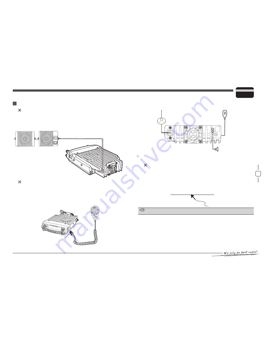
If you plan to use an external speaker, choose a speaker with an 

impedance of 8 Ω. The external speaker jack accepts a 3.5 mm (1/8") 

mono (2-conductor) plug.

For voice communications, connect a microphone equipped with 

an 8-pin modular plug into the modular socket on the front of the 

main unit. Press firmly on the plug until the locking tab clicks. Attach 

the supplied microphone hanger in an appropriate location using the 

screws included in the screw set.

To untilize the QPS588UV software, you must first connect the 

transceiver to your PC then using an optional programming cable 

PC50 (via Data socket ).

Please use QPS-588UV software for programming. 

Initial Installation

exteRnAl SpeAkeR

MicRophone

pc connectinG

Ask your dealer about purchasing a Programming Cable PC51.

AcceSSoRieS connectionS

SP-02

http://www.qxdz.cn

Microphone

connector

External speaker[SP-02]

Microphone[QHM-04]

Antenna[QCA-02]

NOTE

Summary of Contents for AT-588UV

Page 1: ...Dual Band FM Transceiver USER S MANUAL...

Page 2: ......

Page 3: ...Apply To This Manual AT 588UV Mobile radio Nice Housing Stoutness Stability Advanced and Reliable functions Perfect Valuable Approval AT 588UV mobile radio especially designs for drivers and it pursue...

Page 4: ...flexible installation Though friendly design for user this transceiver is technically complicated and some features may be new to you Consider this manual to be a personal tutorial from the designers...

Page 5: ...elch Off Squelch Off Momentary 12 Transmitting 12 Shortcut Operations 13 Squelch level Setup 13 Transmit DTMF 2TONE 5TONE signaling 13 High Mid Low Power Switch 13 Frequency Reverse 13 Band width Sele...

Page 6: ...SELF ID ENQUIR 26 TOT Time out timer 26 VFO Frequency Linkage 26 Wide Narrow band 26 Cross Band repeat 27 LCD backlight 27 Keypad backlight brightness 27 Calling Record 27 AM Function 28 Automatic AM...

Page 7: ...operation mode for option Distribute buttons reasonably convenient for operation Adopt superior quality material better technology and direct flow heat sink to ensure stable and durable operation 758...

Page 8: ...User Manual Cloning Cable CP51 Programming Software QPS 588UV Car Antenna QCA 02 Car Antenna QCA 03 Mobile Mounting Bracket QMB 01 DC Power Cable with Fuse Holder QPL 01 Microphone QHM 04 with DTMF k...

Page 9: ...cation that is shielded from direct sunlight Install the mounting bracket in the vehicle using the supplied self 111 tapping screws 4pcs and flat washers 4pcs Position the transceiver then insert and...

Page 10: ...e box Don t forget to reinforce whole cable In order to avoid the risk of short circuit please cut down 333 connection with negative of battery then connect with radio Confirm the correct polarity of...

Page 11: ...t Use the supplied DC power cable to connect the transceiver to a regulated power supply Do not substitute a cable with smaller gauge wires Fixed Station Operation In order to use this transceiver for...

Page 12: ...e transceiver via feed lines having The possible locations of antenna on a car are shown as following 3 Initial Installation REPLACING FUSES If you use the transceiver for a long period when the vehic...

Page 13: ...ch the supplied microphone hanger in an appropriate location using the screws included in the screw set To untilize the QPS588UV software you must first connect the transceiver to your PC then using a...

Page 14: ...y press to change H L power for present channel Long press it to turn On Off Talk Around Function 9 Left V M Key n standby press to switch between channel mode and VFO mode Long press it to set Wide N...

Page 15: ...en the Offset function is ON 6 Appears while transmitting 7 Displays the Main channel 8 Displays the operating frequency channel name 9 Displays when receiving a signal or Monitor is ON 10 Signal stre...

Page 16: ...FO frequency or DTMF dial out etc 5 A B band Choose left band or right band as Main band 6 Band Indicator The indicator light on for Main band 7 TX RX Indicator Light green while receiving Light red w...

Page 17: ...crease the frequency by one step size Hold UP DOWN key will adjust the frequency continuously When the Band lockout function is on the input or adjusting of frequency band The right band only limited...

Page 18: ...er 1 second then repeater above operation will switch the right band between 136 174Mhz 400 490Mhz 5 Basic Operations Receiving If the transceiver has set at higher squelch level it may fail to hear t...

Page 19: ...power on current channel is low Output power for each level HIGH MID1 MID2 LOW VHF 50W VHF 20W VHF 10W VHF 5W UHF 40W UHF 20W UHF 10W UHF 5W In channel mode this operation is for temporary use only T...

Page 20: ...r flashes Turn selector knob to select the channel number to store If the 333 storage has data the LCD will display the frequency otherwise will display Press 444 key the LCD display MEN IN the channe...

Page 21: ...ld selector knob for over 0 5 second to store setup and exit This transceiver has automatic offset function When this function is on the transceiver will automatically transmitting with RX frequency o...

Page 22: ...n the CPU clock disturbs the working frequency turn on this function will cut the disturbing Press 111 key to enter function menu Turn the Main band selector knob to 222 choose No 06 menu the LCD disp...

Page 23: ...ain band selector knob to choose wanted value 444 OFF Turn off CTCSS DCS encode CTCSS Choose CTCSS encode DCS Choose DCS encode Press the Main band selector knob to enter the menu 555 Switch the Main...

Page 24: ...d frequency DC IN display sub bad voltage OFF turn off display for sub Band Press the Main band selector knob or 555 key to store value and back to function menu Press key or hold selector knob for ov...

Page 25: ...ss PTT will transmit with selected DTMF code 06 16 total 16 group of DTMF code DTMF Encode Transmitting Time DTMF Encode setup When the selected group is empty the 555 LCD displays Press the selector...

Page 26: ...TBST Press the Main band selector knob to enter function setup 333 Switch the Main band selector knob to choose wanted frequency 444 1000 Pilot Frequency is 1000Hz 1450 Pilot Frequency is 1450Hz 1750...

Page 27: ...E displays 2T means 2TONE In VFO mode long press this key the step size change to 10Mhz short press Frequency reverse function when current channel is setup with offset direction and offset frequency...

Page 28: ...y or hold selector knob for over 0 5 second to store setup and exit Press 111 key to enter function menu Turn the Main band selector knob to 222 choose No 23 menu The LCD displays SQL Press the Main b...

Page 29: ...ion menu then press key or hold selector knob for over 0 5 second to store setup and exit Sub band mute setup Editing Channel Name 7 Press 111 key to enter function menu Turn the Main band selector kn...

Page 30: ...store setup and exit Press 111 key to enter function menu Turn the Main band selector knob to 222 choose No35 menu The LCD displays SCAN M Press the Main band selector knob to enter function setup 333...

Page 31: ...tion number and frequency If press key it will change to VFO mode Press the Main band selector knob or 555 key to store value and back to function menu Press key or hold selector knob for over 0 5 sec...

Page 32: ...ter function menu Turn the Main band selector knob to 222 choose No42 menu The LCD displays VFOTR Press the Main band selector knob to enter function setup 333 Switch the Main band selector knob to ch...

Page 33: ...r knob for over 0 5 second to store setup and exit key to store value and back to function menu Press key or hold selector knob for over 0 5 second to store setup and exit Press 111 key to enter funct...

Page 34: ...password function is on correct password shall be input after power on The password shall be programmed before using this function 7 General Setting Press 111 key to enter function menu Turn the Main...

Page 35: ...displays MID2 the transmitting power on current channel is middle 2 When LCD displays LOW the transmitting power on current channel is low TONE CTCSS DCS code setup In standby press the key programmed...

Page 36: ...rn off squelch you can hear very weak signal repeat the above function to turn on squelch TBST Transmit tone burst in standby press the key programmed as TBST function to transmit selected tone burst...

Page 37: ...me When the transmission is successfully finished the master and slave unit both display PASS Turn off the power disconnect the cable and repeat step 2 to step 3 operations to clone the next slave uni...

Page 38: ...dicated then click OK to start programming software As pic 2 According to instruction select correct COM Port As pic 3 then click 444 OK to start programming software NOTE Even in same computer the se...

Page 39: ...y is too dim Dimmer setting is LAMP L Please make the dimmer setting LAMP H d No sound comes from speaker Squelch is muted Decrease squelch level Tone or CTCSS DCS squelch is active Turn CTCSS or DCS...

Page 40: ...Dimensions WxHxD 139 W x40 H x212 D mm Weight about 1 14kg 12 Specifications Receiver ETSI EN 300 086 Wide band Narrow band Sensitivity 12dB SINAD 0 25 V 0 35 V Adjacent Channel Selectivity 70dB 60dB...

Page 41: ...51 052 053 054 055 056 057 060 061 062 063 064 065 066 067 070 071 072 073 074 075 076 077 100 101 102 103 104 105 106 107 110 111 112 113 114 115 116 117 120 121 122 123 124 125 126 127 130 131 132 1...

Page 42: ...525 526 527 530 531 532 533 534 535 536 537 540 541 542 543 544 545 546 547 550 551 552 553 554 555 556 557 560 561 562 563 564 565 566 567 570 571 572 573 574 575 576 577 600 601 602 603 604 605 606...

Page 43: ...A1 0 12 09...

Reviews: