background image

WARMER DRAWER

8

P/N 1010889 Rev. B 09/16

WARNING

Turn the unit off, disconnect the power source and 

allow the unit to cool down before performing any ser-

vice or maintenance on the unit.

MAINTENANCE

Cleaning

DAILY

  1.  Turn the unit off, unplug the power cord, and 

allow the unit to cool down before proceeding.

  2.  Remove all parts from inside the Warmer Drawer.  

Wash all parts in soap and water, rinse in clear 

water, and wipe dry.

  3.  Wipe the exterior of unit with a damp cloth or 

stainless steel cleaner, then wipe dry with a 

clean, dry cloth.

  4.  Re-install all parts into Warmer Drawer.

NOTE: Failure to porperly clean and dry the parts 

prior to re-assembly may result in the accumula-

tion of water/moisture overnight.  This may lead to 

permanent damage of the equipment finish and its 

accessories.  This damage is permanent and not 

covered by warranty.

CAUTION

To prevent damage to the unit, do not use abrasive 

cleaners on the unit.

WARNING

Use caution when using caustic cleaning solutions.  

Read all manufacturer label instructions to avoid per-

sonal injury.

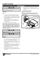
Figure 4. Removing Drawer

Press down simultane-

ously on both the left and 

right interlocking tabs to 

release the Drawer

WEEKLY

  1.  Turn the unit off, unplug the power cord, and allow 

the unit to cool down before proceeding.

  2.  Remove all parts from the Warmer Drawer.  Wash 

all parts in soap and water, rinse in clear water, 

and wipe dry.

  3.  Pull the Drawer out (Figure 4).  Push down simul-

taneously on both the interlocking tabs (above 

each drawer side rail - Figure 4) and pull the 

Drawer away from unit.

  4.  Wipe the interior of the Warmer Drawer with a 

clean, damp cloth.  Then, whipe dry with a clean, 

dry cloth.

  3.  Wipe the exterior of unit with a damp cloth or 

stainless steel cleaner, then wipe dry with a clean, 

dry cloth.

  4.  Re-install all parts into unit.

Replacing Components

NOTE: It is recommended that all service proce-

dures be performed by a qualified authorized ser-

vice technician.

Drawer 

Side 

Rail

Drawer

Summary of Contents for WD-20 Series

Page 1: ...S T E C US INTERTEK P N 1010889 Rev B 09 16 WD 20 WD 21A WD 35A owner s manual Warmer Drawer without water tray Manufacturing Numbers 9400130 9400132 9400133 9400134 9400136 9400140 9400142 9400144 9100145 9400146 9400150 9400152 9400154 9100155 9400156 www antunes com ...

Page 2: ...s when filing a claim Freight damage claims are the responsibility of the purchaser and are not covered under warranty The warranty does not extend to Damages caused in shipment or damage as result of improper use Installation of electrical service Normal maintenance as outlined in this manual Malfunction resulting from improper maintenance Damage caused by abuse or careless handling Damage from m...

Page 3: ... to the proper operation of the equipment Failure to observe may result in damage to the equipment WARNING HOT SURFACE WARNING Indicates infor mation important to the handling of equip ment and parts Failure to observe caution could result in personal injury IMPORTANT SAFETY INFORMATION Service Technical Assistance If you experience any problems with the installation or operation of your unit cont...

Page 4: ... Communication Standard See Hazard Communication Standard manual for the appropriated Material Safety Data Sheets MSDS The unit should be grounded according to local electrical codes to prevent the possibil ity of electrical shock It requires a grounded receptacle with separate electrical lines pro tected by fuses or circuit breaker of the prop er rating All electrical connections must be in accor...

Page 5: ...embly Only C F 5 15P 15 Amp 250 VAC Non Locking Assembly Only H G BS 1363 Fused Permaplug 16 Amp 250 VAC Assembly Only WHT BLK GRN Model Width A Depth B Height C WD 20 18 3 4 476 mm 21 533 mm 10 5 8 270 mm WD 21A 22 3 16 564 mm 17 432 mm 10 3 8 264 mm WD 35A 32 1 2 826 mm 17 432 mm 10 3 8 264 mm Model Mfg No Volts Watts Amps Hertz WD 20 CF 9400130 120 500 4 2 50 60 WD 20 HC 9400132 230 500 2 2 50 ...

Page 6: ...ated surfaces Do not allow cord to hang over edge of table or counter Connect the unit to the power supply Refer to the specification plate for the proper voltage INSTALLATION CAUTION All electrical connections must be in accordance with local electrical codes and any other applicable codes WARNING ELECTRICAL SHOCK HAZARD FAILURE TO FOLLOW THE INSTRUCTIONS IN THIS MANUAL COULD RESULT IN SERIOUS IN...

Page 7: ... to 30 45 minutes 1 Turn the Rocker Switch power On Off to ON 2 Set the thermostat control to the desired setting The heater ON light will be lit 3 Load product into the drawer Hi Limit Reset A Hi Limit Thermostat with a reset switch is contained in the heating circuit If the unit should overheat for any reason the Hi Limit Thermostat opens and cuts off power to the Heating Element To reset the Hi...

Page 8: ...the unit do not use abrasive cleaners on the unit WARNING Use caution when using caustic cleaning solutions Read all manufacturer label instructions to avoid per sonal injury Figure 4 Removing Drawer Press down simultane ously on both the left and right interlocking tabs to release the Drawer WEEKLY 1 Turn the unit off unplug the power cord and allow the unit to cool down before proceeding 2 Remov...

Page 9: ...ance person or Authorized Service Agency for service Loose broken or burnt wiring in Heating Circuit Contact your maintenance person or Authorized Service Agency for service Faulty Heating Element Contact your maintenance person or Authorized Service Agency for service Faulty Thermostat Control Contact your maintenance person or Authorized Service Agency for service Product becomes hard and dry Th...

Page 10: ...T 5 4 2 1 POWER SWITCH WHT WHT BLK BLK GND GRN TERMINAL POWER BLOCK CORD WHT BLK HI LIMIT THERMOSTAT INDICATOR LIGHT HEATER BLK BRN WHT BLU GRN GRN YEL ELEMENT UNLESS OTHERWISE SPECIFIED NOTE ALL WIRES TO BE 16 GA TFE 200 C THERMOSTAT WIRING DIAGRAM ...

Page 11: ...11 WARMER DRAWER P N 1010889 Rev B 09 16 REPLACEMENT PARTS WD 20 7 6 17 31 32 34 18 3 5 29 1 2 29 4 19 8 13 20 9 22 21 16 15 14 26 29 29 29 12 25 23 23 24 33 30 ...

Page 12: ... Element 230 Volt 500 Watt 1 13 4060323 Indicator Light Heater ON 120 Volt 1 4060229 Indicator Light Heater ON 230 Volt 1 14 0011825 Drawer Assembly Incl 15 16 1 15 0501662 Drawer Front 1 16 210K128 Handle Kit 1 17 7000136 Terminal Block Kit 1 18 4030291 Thermostat Hi Limit 1 19 1000925 Label 1 20 2100110 Knob F 1 2100224 Knob C 1 21 300P108 Tube Clip Thermostat Bulb 1 22 300P107 Tube Clip Heating...

Page 13: ...13 WARMER DRAWER P N 1010889 Rev B 09 16 REPLACEMENT PARTS WD 21A 35A 7 6 17 32 33 18 3 5 29 12 1 2 29 24 23 16 15 27 26 23 4 19 8 13 20 9 22 21 29 25 31 30 31 14 ...

Page 14: ...Element 1400 watts 120 Volt WD 35A 1 4030176 Heating Element 1530 watts 230 Volt WD 35A 1 13 4060323 Indicator Light Heater ON 120 Volt 1 4060229 Indicator Light Heater ON 230 Volt 1 14 0011831 Drawer Assembly WD 21A Incl 15 16 1 0011839 Drawer Assembly WD 35A Incl 15 16 1 15 0500783 Drawer Front WD 21A 1 0500820 Drawer Front WD 35A 1 16 2100106 Handle 1 17 7000136 Terminal Block 1 18 4030291 Ther...

Page 15: ...15 WARMER DRAWER P N 1010889 Rev B 09 16 NOTES ...

Page 16: ...ease sheet and con veyor belt wraps This warranty does not pay travel mileage or any other charges for an authorized service agency to reach the equipment location 2 Roundup reserves the right to make changes in design or add any improvements on any product The right is always reserved to modify equipment because of factors beyond our control and government regulations Changes to update equipment ...

Reviews: