background image

4.10  Checking Cylinder Piston Seals

4.10.1  Power Down Models

1.  First, check the lowering valve.  Make sure it is operating 

correctly, and the valve is not sticking or dirty. Replace 

the valve if necessary. Refer to “4.7 Checking Valve 

Cartridge and Solenoid” on page 12.

2.  Raise the platform approximately 12 inches off of the 

floor.

3.  Place a floor jack securely under the platform to support 

its full weight. An overhead lifting device could also be 

used.

4.  Raise the floor jack until the platform begins to raise 

slightly.

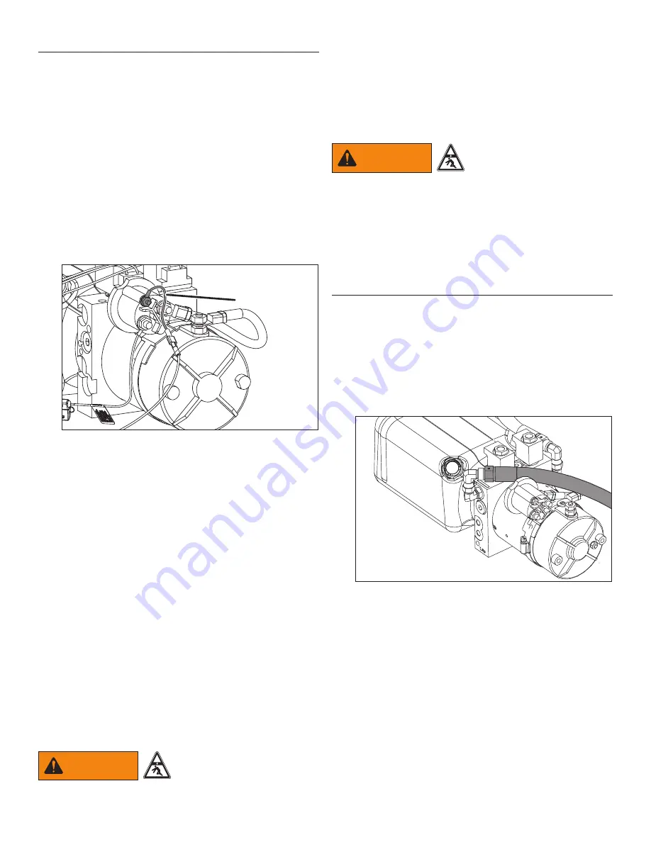
5.  Disconnect the white wire from the motor start solenoid. 

Place electricians tape around the end of the wire to 

prevent it from making a ground connection.

White wire to 

motor start 

solenoid

759a

6.  With the platform securely supported by the lifting 

device, activate the control switch in the DOWN position 

and hold the switch for 15 seconds. This will release 

any pressure in the power down hose.

7.  Now activate the control switch in the UP position and 

hold it for 15 seconds. This will release any pressure in 

the power up hose.

8.  Repeat holding the control switch in the DOWN position 

for 15 seconds and again in the UP position for 15 

seconds. This should release any trapped pressure.

9.  Carefully remove the flow control valve from the rod end 

of the cylinder. Plug or cap the fitting.

10. Remove the hose from the cap end of the cylinder 

and attach a temporary hose to catch any potential 

leakage from the cylinder. Place the end of the hose in 

a minimum one gallon container.

11. Lower the floor jack or lifting device.
12. Major seal damage will be apparent right away as 

the platform would begin to slowly lower and fluid will 

come out of the hose. Less extensive damage may 

take longer to be seen. Allow the platform to sit for 

several hours or overnight.

WARNING

Make sure nothing or no 

one could accidentally go 

under the platform while the 

hoses are disconnected.

13. If the platform does not lower, the seals are not the 

problem, most likely it is a faulty lowering valve.

14. Reconnect the white wire to the motor start termial. 

Raise and lower the platform several times to remove 

any trapped air.

4.10.2  Gravity Down Models

1.  Completely raise the platform. 

WARNING

Do not stand under the 

platform.

2.  Remove breather tube from the cap end of the cylinder 

and attach a short piece of hose routed into a hand-

held container.

3.  Activate the control switch in the UP position.
4.  If oil is continuously pumped out of the hose, replace 

the cylinder.

4.11  Checking System Pressure

For gravity down systems, there is only one relief valve 

(power up).  Power down models have two relief valve 

settings; one for raising the platform (power up, upper 

adjusting screw) and one for lowering the platform (power 

down, lower adjusting screw).

To check the “power up” pressure setting:

1.  Place the liftgate on the ground and remove the 

pressure hose from the power up port of the pump.

725a

    Power UP Model Pressure Hose Shown

2.  Install a T-fitting (customer supplied) into the power up 

port.

3.  Connect a pressure gauge and reconnect the hydraulic 

hose. 


The pressure gauge must be rated above the maximum 

pressure of the liftgate.  For example, use a 4000 

psi pressure gauge on a 3000 psi maximum capacity 

liftgate.

4.  Raise the liftgate and check the pressure on the gauge.

Summary of Contents for AC-1600

Page 1: ...Made in the USA AC AC 1600 AC 2000 AC 2500 Quality Reliability Customer Service MAINTENANCE MANUAL...

Page 2: ......

Page 3: ...l Tank Safety 7 2 3 4 Cutting Torch Welding Safety 7 2 4 Welding or Grinding Galvanized or Stainless Steel Material 8 2 4 1 Galvanized Metal 8 2 4 2 Stainless Steel 8 3 Nomenclature 8 4 Maintenance 10...

Page 4: ...rovide protection against rear impact and comply with State and Federal standards in your area Anthony Liftgates offers a bolt on bumper which meets the requirements of this standard 1 4 If Maintenanc...

Page 5: ...be avoided by being alert and recognizing potentially hazardous situations The safety information in this manual serves as a basic guide in an attempt to prevent injury or death Anthony Liftgates can...

Page 6: ...t weld No smoking No open flame No alcohol No drugs 2 2 3 Hazard Avoidance Safety alert symbol Slipping injury Tripping injury Pinch point hazard Pinch hazard foot Dangerous fumes Adequate ventilation...

Page 7: ...arks and or component damage resulting in loss of vehicle control serious injury or even death CAUTION OEM OEM If replacement parts are necessary genuine factory OEM replacement parts must be used to...

Page 8: ...Symptoms include headache fever chills muscle aches nausea vomiting weakness and tiredness There are no long term health effects Metal fume fever typically begins about four hours after exposure and f...

Page 9: ...r Cap Reservoir 10 Amp In Line Fuse BLACK wire WHITE wire GREEN wire Power Cord w 200 Amp Fuse 3 3 Power Down Power Unit Nomenclature 370 Power Cord w 200 Amp Fuse Hydraulic Cylinder Control Switch El...

Page 10: ...o possible compatibility problems Use the appropriate viscosity of fluid based on the surrounding climate conditions Viscosity is important because the pump will not cause a temperature increase to th...

Page 11: ...Bolt the new fuse to the cable lugs using the bolts washers and lock washer as shown 6 Slide the heat shrink tube over the fuse hardware and lugs Using a heat gun apply heat evenly to shrink the tubi...

Page 12: ...ement part A 176315 7 Remove the valve cartridge from the pump body Replacement part A 130216 lowering valve or A 130215 raising valve 8 Clean the cartridge and blow it dry with compressed air not gre...

Page 13: ...ng device 12 Major seal damage will be apparent right away as the platform would begin to slowly lower and fluid will come out of the hose Less extensive damage may take longer to be seen Allow the pl...

Page 14: ...liftgate with load If liftgate performs well set pump pressure according to factory settings 858 857 7 6 Check the power down relief valve pressure in the same way as the power up by installing a T f...

Page 15: ...ut off switch to power unit To verify a faulty cable connect motor directly to a spare battery using the procedure in the Maintenance section Replacement part A 133604 Corroded or loose wire connectio...

Page 16: ...on ground check remove and clean valve cartridge using the procedure in section 4 9 Checking Valve Cartridge and Solenoid on page If plunger will not move freely replace Replacement part A 130216 Cyli...

Page 17: ...he cylinder repair is not practical Refer to section 4 12 Checking Cylinder Piston Seals on page Replacement part A 130113 Cylinder 3 or A 130114 Cylinder 4 Hydraulic pump is worn Replace power unit R...

Page 18: ...ly replace the valve 4 14 Checking Flow Control Valve on page Replacement part A 130102 Lowering valve power down models only Solenoid or cartridge may need cleaning or replacement Refer to section 4...

Page 19: ...cals 6 7 and 8 are attached to the lift arms and platform 892 A 150601 7 6 8 3 Make sure factory installed decals 9 10 11 and 12 are installed on and inside the power unit and on the adapter frame tub...

Page 20: ...ake sure the proper M A X I M U M CAPACITY decal is placed on the truck for the appropriate lifting capacity of the liftgate being installed Do not put a higher rated decal on a liftgate with a lower...

Page 21: ...10 A 131133 This hydraulic reservoir is filled with Kendall Glacial Blu hydraulic fluid Use ONLY the same or equivalent fluid A 131133 11 A 131001 attached to control cable 12 A 131125 attached only t...

Page 22: ...X 615 P O BOX 615 PONTIAC IL 61764 0615 PONTIAC IL 61764 0615 PH 815 842 3383 PH 815 842 3383 FAX 815 844 3612 FAX 815 844 3612 TOLL FREE 800 482 0003 TOLL FREE 800 482 0003 WWW ANTHONYLIFTGATES COM W...

Reviews: