9
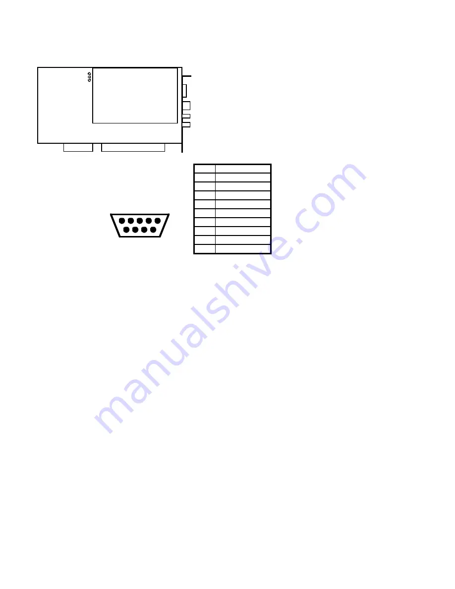
Figure 4: SX-7 Connector Locations
Headphones
DB-9 Balanced Out
Unbalanced Right
Unbalanced Left
SX-7
JP1
1
LEFT
RIGHT
G ND
Pin
Assignment
1
Gnd
2
3
nc
4
Right Out -
5
Left Out -
6
nc
7
nc
8
Right Out +
9
Left Out +
DB-9
Female
Balanced Analog I /O Connector
1
2
3
4
5
6
7
8
9


