ANTEK ISK 100 User Manual Download Page 6


H

ARDWARE 

I

NSTALLATION 

G

UIDE


2.1


R

EMOVING THE 

L

EFT 

P

ANEL


Lay the case on its right side, with the I/O panel facing you.  
You will be removing the left panel (the one with the fan) 
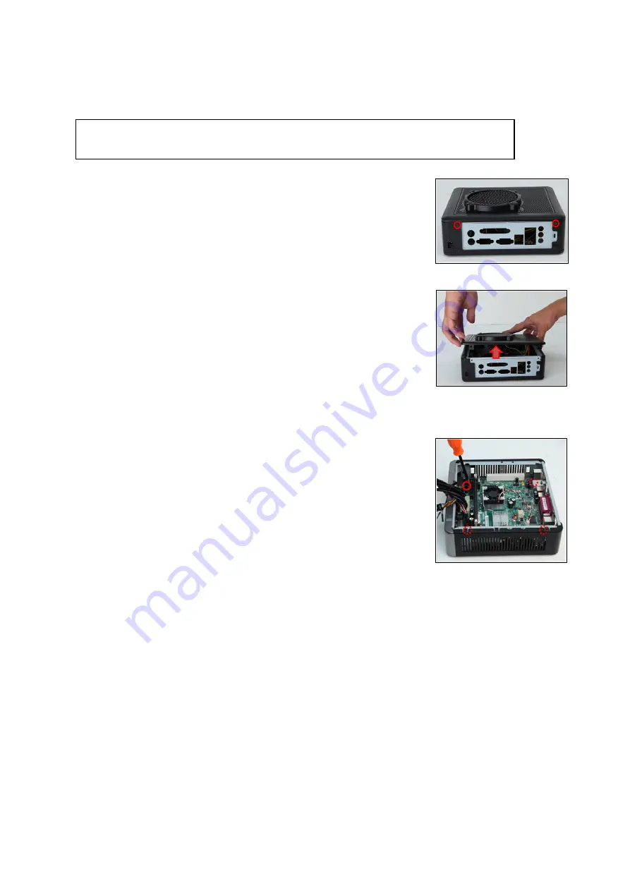
  

1.


Remove the two screws from the rear of the panel.  

2.


Remove the panel, making sure to lift the back portion first. If this is 
the first time you are opening the case, remove the drive cable 
bundle and tool bag from the inside of the case and set them aside. 

Note

: Do not use your fingernails to pry or lift the panels. 


2.2


M

OTHERBOARD 

I

NSTALLATION


1.   Lay the case down, with the open side facing up.  
2.   Make sure you have the correct I/O panel for your motherboard. If 

the panel provided with the case isn’t suitable, please contact your 
motherboard manufacturer for the correct I/O panel. Install the I/O 
panel at the rear of the case. 

3.   Align your motherboard with the motherboard standoff holes 

located at the rear of the case.  

4.   Screw in your motherboard to the standoffs with the provided 

Phillips-head screws.  

5.   Attach the 24-pin connector of the included cable bundle to the 

motherboard and connect the 18-pin connector to the already 
installed PCB in the case.  

6.   Your motherboard is now installed. Refer to section 3.1 for 

instructions on how to connect the I/O panel cables. 


Note: 

Do not install the stand prior to installing hardware. You will need to remove the 

stand in order to access the inside of the case. 

Remove these case screws 

Lift the back up first 

Motherboard screw locations 

All manuals and user guides at all-guides.com

all-guides.com

Summary of Contents for ISK 100

Page 1: ...ISK 100 ISK Series USER S MANUAL All manuals and user guides at all guides com a l l g u i d e s c o m...

Page 2: ...the Left Panel 5 2 2 Motherboard Installation 5 2 3 Internal 2 5 Device Installation 6 CONNECTING THE FRONT I O PORTS 3 1 USB 2 0 Ports 7 3 2 AC 97 HD Audio Ports 7 3 3 Switch and LED Connectors 8 3 4...

Page 3: ...pherals please refer to the user s manuals that come with those components Although care has been taken to prevent sharp edges in your Antec case we strongly recommend taking the appropriate time and...

Page 4: ...rnal drive bays Motherboard Size Mini ITX Front I O Panel 4 x USB 2 0 AC 97 HD Audio In and Out Power Supply 90 watt internal adapter 1 2 DIAGRAM 1 1 x 100 mm 2 speed side fan 2 2 x 2 5 internal drive...

Page 5: ...5 efficient at 100 VAC and 240 VAC input voltage and maximum load A variety of industrial grade safety circuitry will help protect your computer Over Voltage Protection OVP Short Circuit Protection SC...

Page 6: ...case isn t suitable please contact your motherboard manufacturer for the correct I O panel Install the I O panel at the rear of the case 3 Align your motherboard with the motherboard standoff holes l...

Page 7: ...ive will be utilized 5 Secure your hard drive s to the bracket using the supplied black screws Fasten screws to the bottom of the hard drive The top of the hard drive will face the motherboard and the...

Page 8: ...el USB cables to the USB header pins on your motherboard Check the motherboard manual to ensure that it matches the table below 3 2 AC 97 HD AUDIO PORTS There is an Intel standard 10 pin AC 97 connect...

Page 9: ...ng work so that you can recover if your work gets disturbed 1 Determine which wires you need to remove in order to rewire your plug to match the USB pin outs on your motherboard refer to your motherbo...

Page 10: ...The default speed setting is Low The fan is mounted so that air blows out of the case Size 100 mm x 12 mm 2 speed fan Rated Voltage 12V Operating Voltage 10 8V 13 2V Speed RPM Input Current Airflow St...

Page 11: ...7 1752 Customer Support US Canada 1 800 22ANTEC customersupport antec com Europe 31 0 10 462 2060 europe techsupport antec com www antec com Copyright 2010 Antec Inc All rights reserved All trademarks...

Reviews: