Antec Nineteen Hundred User Manual Download Page 13

13 


2.5 


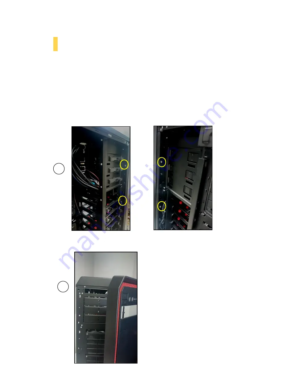
External 5.25” Device Installation 

 
To install a 5.25” drive, you will need to remove the side panel and open the front door.  
 (For side panel removal, please see Section 2.1.) 
 

1.


For front panel removal, please remove the screws on the both sides first 

2.


With the side panel off, carefully push the drive bay cover out of the drive bay.  

3.


Slide your 5.25” drive through the front of the chassis until it lines up flush with the front bezel. 
You will feel the drive lock into position. 

4.


If you need more clearance on the inside of the chassis for your drive, pull the drive bay tab on 
the inside of the chassis toward you and push the drive in further. 


To install a 5.25

” drive, please open the front 

door.


Before open the front door, please remove the screws on the 

both sides, the yellow circles show screw located


Summary of Contents for Nineteen Hundred

Page 1: ...NINETEEN HUNDRED User Manual...

Page 2: ...vance silent Fluid Dynamic bearing chassis fan which can provide lowest fan acoustic to under 18dB A Finally the Nineteen Hundred is constructed of durable SECC steel that lasts for builds to come Alo...

Page 3: ...Coolers 11 2 4 Power Supply Installation 12 2 5 External 5 25 Device Installation 13 2 6 Internal 3 5 2 5 Device Installation 15 2 7 Cable Management 17 Section 3 Front I O Ports 3 1 USB 2 0 19 3 2 U...

Page 4: ...4 Section 1 Introduction NINETEEN HUNDRED User Manual...

Page 5: ...ays 4 3 x 120 mm front intake fans 5 2 x 120 mm HDD internal fan mounts 6 1 x 120 mm Rear exhaust fan 7 2 x 120 mm top exhaust fans 8 Motherboard Mount SSI CEB E ATX ATX Micro ATX Mini ITX 9 CPU cutou...

Page 6: ...20mm top exhaust FDB silent fan 1200 r p m 18dB Drive Bays 3 x 5 25 tool less drive bays 12 x 3 5 2 5 tool less HDD bays 2 x 2 5 HDD bays Expansion Slots 9 Motherboard Size SSI CEB E ATX Standard ATX...

Page 7: ...unpainted metal surface such as a connector or screw on the back of this computer or by using a wrist grounding strap Before you connect a cable ensure that both connectors are correctly aligned and o...

Page 8: ...8 Section 2 Hardware Installation NINETEEN HUNDRED User Manual...

Page 9: ...rear of the chassis CAUTION Do not use your fingernails to pry or lift the panels Damage to the panels or injury to your fingernails may result 2 2 Motherboard Installation Before proceeding Check the...

Page 10: ...nstall standoffs as needed and put the motherboard in 3 Screw your motherboard into the standoffs with the provided motherboard mounting screws Install the motherboard standoffs by aligning the mother...

Page 11: ...el LGA 1155 1156 1366 2011 AMD AM2 AM3 AM2 AM3 FM1 Your unit may not contain the LGA 2011 mounting bracket To acquire this please contact Antec customer support information listed at end of manual Be...

Page 12: ...H2O 920 for more information 4 Prepare the retention ring according to the CPU socket you re using 5 Complete installation according to the KUHLER H2O instructions 2 4 Power Supply Installation 1 Wit...

Page 13: ...y cover out of the drive bay 3 Slide your 5 25 drive through the front of the chassis until it lines up flush with the front bezel You will feel the drive lock into position 4 If you need more clearan...

Page 14: ...14 See step 3 above if you need more clearance for your drive C Make sure to also remove the side panel as well see Section 2 1 for more information D...

Page 15: ...E in Section 1 3 secure your 3 5 drive to the tray We recommend using your hand to find the exact threading of the drive s holes then using a screwdriver to completely secure your drive Do not over t...

Page 16: ...the 2 5 tray holes 3 Using the 2 5 drive screws F in Section 1 3 secure your 3 5 drive to the tray with a screwdriver 4 Now that your drive is secure to the tray pinch the ends of the tray and insert...

Page 17: ...he hole toward the right side of the case Use the zip ties provided to hold your cables in place Zip ties can be anchored to tiedown locations located on the back of the motherboard panel For cables w...

Page 18: ...18 Section 3 Front I O Ports NINETEEN HUNDRED User Manual...

Page 19: ...nual to ensure that it matches the table below 3 2 USB 3 0 The NINETEEN HUNDRED comes with four front panel USB 3 0 ports and includes an internal motherboard connector To access USB 3 0 capability fr...

Page 20: ...dio cable Consult your motherboard or sound card manual for the pin out positions Even if your system supports both standards only use one connector 3 4 Power Switch Reset Switch Hard Disk Drive LED C...

Page 21: ...res you need to remove in order to rewire your plug to match the USB pin outs on your motherboard refer to your motherboard user s manual Working on one connector at a time use a very small flathead s...

Page 22: ...22 Section 4 Cooling System NINETEEN HUNDRED User Manual...

Page 23: ...PM 10 0 30A 1 43 m min 51 2CFM 1 21 mm H2O 0 05 inch H2O 27 9 dBA 3 6W Low 900RPM 10 0 18A 0 84 m min 30 1CFM 0 49 mm H2O 0 02i nch H2O 16 9 dBA 2 2W 4 2 Optional Fans The NINETEEN HUNDRED includes mo...

Page 24: ...ED has two speed switches on the rear of the case that let you choose the speed best suited to your need Low mode 600 R P M High mode 1200 R P M Secure an intake fan into place by aligning it with the...

Page 25: ...er system temperatures and possible stability problems We recommend checking the air filter at least once a month initially The frequency will change depending on system usage users whose systems run...

Page 26: ...nsport To remove the PSU filter push the ends of the filter down then pull the filter toward you using the tab outside of the chassis You can also lock the filter by pushing up on the tab once the fil...

Page 27: ...el 49 40 226139 22 fax 31 0 10 437 1752 Technical Support US Canada 1 800 22ANTEC customersupport antec com Europe 31 0 10 462 2060 europe techsupport antec com www antec com Copyright 2011 Antec Inc...

Reviews: